
Monday to Saturday - 8:00 -17:30

An apprentice stands beside a running diesel engine in the workshop. From the outside, it seems like nothing more than noise, vibration, heat, airflow, and exhaust. But inside, a highly precise sequence is repeating many times every second. What is actually happening inside the engine while it is running?
To understand faults, technicians must first understand normal operation. Before you can accurately diagnose why an engine is failing, you must deeply understand Diesel Engine Operation and how the system is designed to work when healthy.
What Diesel Engine Operation Means
A diesel engine is fundamentally an energy-conversion machine. It converts stored energy into useful mechanical work.
The basic conversion chain during Diesel Engine Operation is:
Chemical Energy in Fuel → Heat from Combustion → Pressure in the Cylinder → Piston Movement → Crankshaft Rotation
For this cycle to occur correctly, it requires:
- the correct sequence of events
- precise timing
- sufficient clean air
- sufficient fuel
- proper compression
- effective cooling and lubrication
Main Internal Components of a Diesel Engine
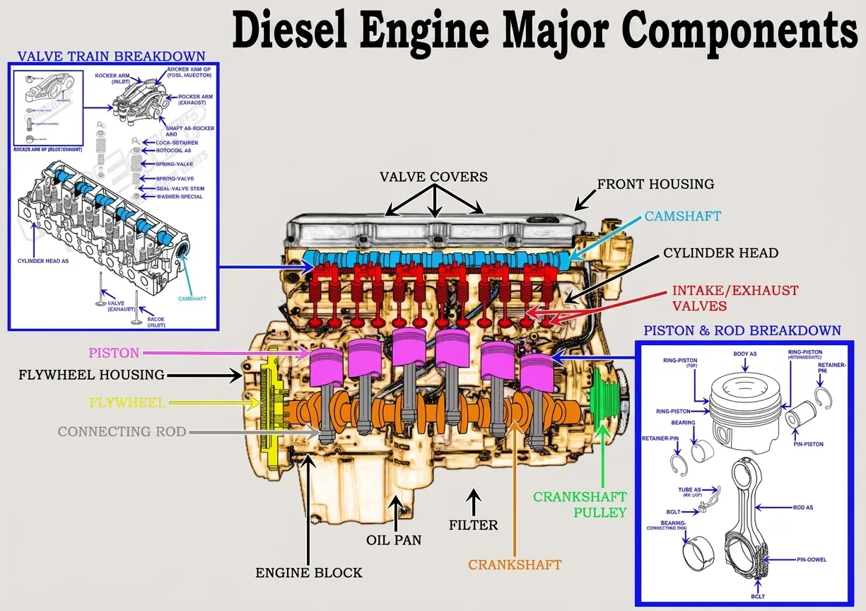
Before learning the operational cycle, it helps to identify the major components inside the engine.
- Cylinder Block: The main engine structure that supports the cylinders and crankshaft.
- Cylinder Head: Closes the top of the cylinders and may contain valves, injectors, coolant passages, and valve-train components depending on engine design.
- Pistons: Cylindrical components that move up and down inside the cylinders.
- Piston Rings: Help seal combustion pressure, control oil, and transfer heat from the piston to the cylinder wall.
- Connecting Rods: Connect the pistons to the crankshaft.
- Crankshaft: Converts the reciprocating movement of the pistons into rotary movement.
- Camshaft: Controls valve timing through the valve train, determining when the intake and exhaust valves open and close.
- Intake and Exhaust Valves: Control the movement of fresh air into the cylinder and exhaust gases out of the cylinder.
- Fuel Injectors: Components that meter and deliver fuel into the combustion chamber according to the engine’s fuel-system design.
- Flywheel: Helps smooth power pulses and connects the engine’s output to downstream systems.
Understanding TDC and BDC
Technicians frequently use two important acronyms to describe piston position:
- Top Dead Center (TDC): The highest position the piston reaches inside the cylinder.
- Bottom Dead Center (BDC): The lowest position the piston reaches inside the cylinder.
During engine operation, the piston repeatedly travels between TDC and BDC.
Understanding these terms is essential because they are reference points for discussing:
- valve timing
- injection timing
- compression
- piston travel
- engine adjustment procedures
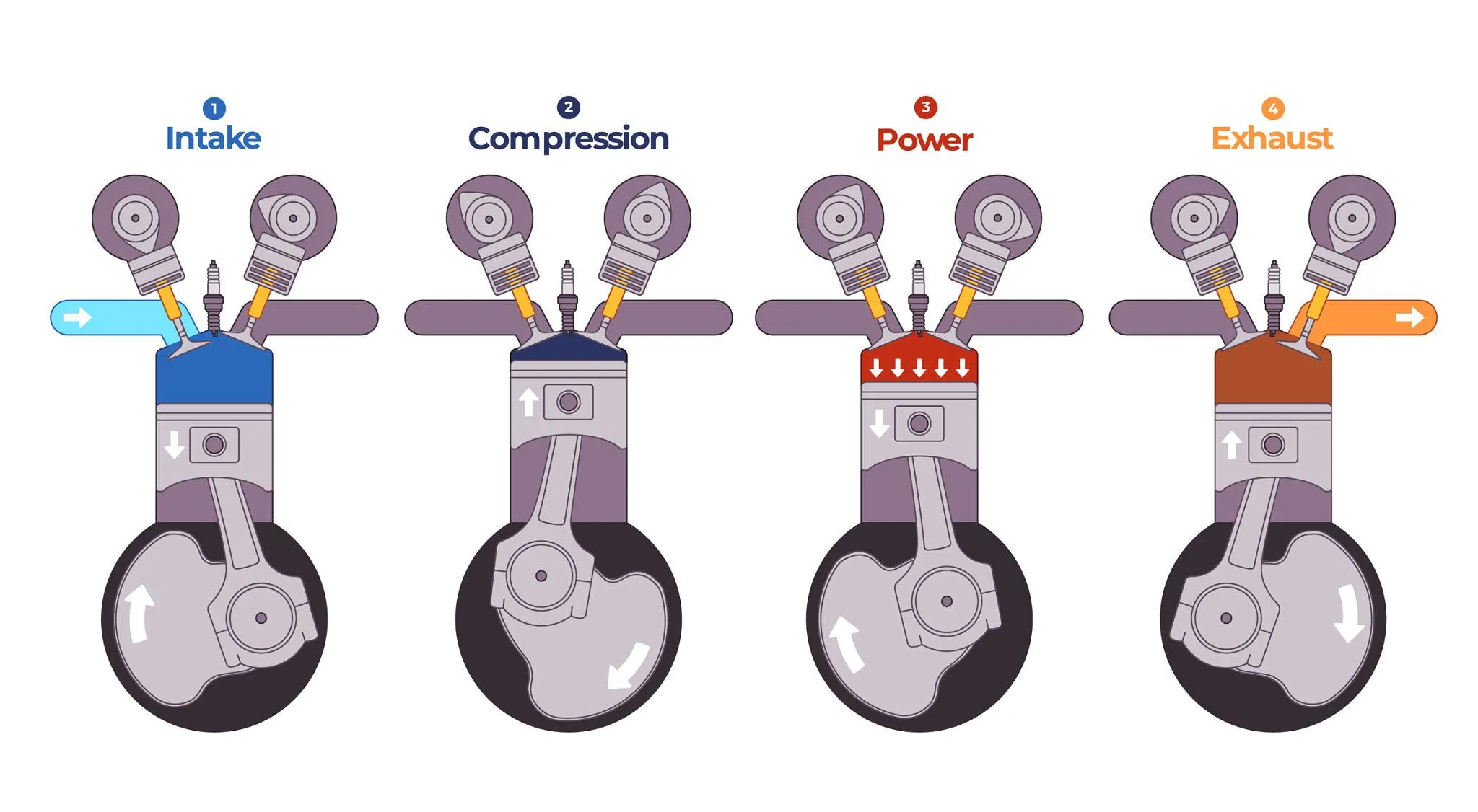
The Four-Stroke Diesel Cycle
Most modern heavy-duty diesel engines operate on the four-stroke cycle. This means the piston must travel up or down four distinct times to complete one power-producing sequence.
Intake Stroke
- The piston moves downward from TDC toward BDC.
- The intake valve is open.
- The exhaust valve is generally closed during the main intake event.
- Fresh air enters and fills the cylinder.
- Where turbocharging is used, this intake air may already be under pressure.
Compression Stroke
- The piston moves upward from BDC toward TDC.
- Both the intake and exhaust valves are closed during the main compression event.
- The trapped air is compressed into a smaller space.
- As the air is compressed, its pressure and temperature rise significantly.
- Proper compression is essential for starting the engine and supporting effective combustion.
Power Stroke
- Near the end of the compression stroke, fuel is injected into the cylinder.
- The fuel atomizes and mixes with the hot compressed air.
- A controlled combustion event begins.
- Cylinder pressure rises.
- The expanding gases push the piston downward toward BDC.
- This downward force transfers through the connecting rod to the crankshaft, generating useful mechanical output.
Exhaust Stroke
- The exhaust valve opens.
- The piston moves upward from BDC toward TDC.
- The upward movement pushes spent exhaust gases out of the cylinder.
- The gases move into the exhaust manifold.
- Where fitted, some exhaust energy drives the turbocharger turbine.
After the exhaust stroke, the cycle repeats continuously. Understanding the four-stroke cycle is central to understanding Diesel Engine Operation.
How the Crankshaft and Camshaft Work Together
For Diesel Engine Operation to function correctly, the mechanical parts must stay synchronized.
The crankshaft follows the movement of the pistons, while the camshaft controls the timing of the intake and exhaust valves.
In a conventional four-stroke engine, the camshaft rotates at half the crankshaft speed.
If this synchronization is incorrect, the engine may suffer from:
- poor starting
- low power
- rough running
- incorrect valve events
- possible internal mechanical damage depending on engine design
Correct timing is therefore essential to normal engine operation.
Why Diesel Engines Use Compression Ignition
Unlike gasoline engines that typically rely on a spark to initiate combustion, diesel engines rely on heat created by compressing air.
The sequence works like this:
Air Enters → Air Is Compressed → Temperature Rises → Fuel Is Injected → Fuel Begins to Burn
During the compression stroke, the temperature of the trapped air rises significantly.
When diesel fuel is injected into sufficiently hot compressed air, the fuel begins to auto-ignite.
Depending on engine design and operating conditions, starting aids such as intake heaters or glow plugs may be used to assist this process in cold conditions.
How Air Moves Through the Engine
A diesel engine requires a sufficient supply of clean air to operate efficiently.
The general airflow path is:
Atmosphere → Air Cleaner → Turbocharger Compressor, where fitted → Charge-Air Cooler, where fitted → Intake Manifold → Cylinder
Clean and unrestricted airflow is critical.
Air filtration removes harmful dirt and abrasive contamination.
Turbochargers compress the intake air so that a greater mass of air can enter the cylinders.
Where fitted, charge-air coolers remove some of the heat created during compression, increasing the density of the intake charge before it reaches the engine.
Restrictions in the air cleaner, damaged intake hoses, or charge-air leaks can reduce the amount of usable air reaching the cylinders and negatively affect performance.
How Fuel Enters the Combustion Chamber
Fuel must move from the storage system to the injector, where it is delivered into the combustion chamber in a form suitable for effective atomization and combustion.
The general fuel path is:
Fuel Tank → Water Separation / Filtration → Supply System → Pressure Generation → Injector → Cylinder
Fuel-system designs vary between manufacturers and engine generations.
Common architectures may include:
- mechanical injection
- electronic unit injectors
- hydraulic-electronic unit injectors
- high-pressure common rail
Regardless of the specific design, fuel must be delivered at the correct time, in the required quantity, and in a form that supports effective atomization and combustion.
What Happens During Diesel Combustion
Diesel combustion is a controlled process.
- Fuel is injected into the hot compressed air.
- The injector breaks the fuel into fine droplets.
- The fuel begins to vaporize and mix with the available oxygen.
- A short ignition delay occurs between the start of injection and the start of combustion.
- Combustion begins.
- Cylinder pressure rises.
- The expanding gases push the piston downward.
This pressure acting on the piston is what allows the engine to create useful mechanical output.
How Torque Is Produced
Heavy equipment relies heavily on torque to perform work.
Torque generation in a diesel engine happens through this sequence:
- cylinder pressure acts on the piston
- the piston pushes through the connecting rod
- the connecting rod applies force to the crankshaft journal
- the crankshaft converts this force into rotational torque
Engine torque depends on multiple design and operating factors, including:
- cylinder pressure
- crankshaft geometry
- engine displacement
- combustion
- engine speed
- air delivery
- fuel delivery
Torque is therefore the result of the complete engine system working correctly, not one single design feature.
Valve Timing: Why Timing Matters
In an actual operating engine, valves do not simply open exactly at TDC and close exactly at BDC.
Manufacturers carefully engineer intake and exhaust valve timing to improve cylinder filling and exhaust flow.
This optimization may include valve overlap, where the intake and exhaust valve events overlap for a short period.
Correct valve timing helps the engine breathe efficiently and supports normal performance.
How the Engine Maintains Speed Under Load
When a machine begins working harder, engine load rises.
For example, when a loader drives into a pile, engine speed may begin to fall as load increases.
The engine-control system responds by adjusting fuel delivery within the engine’s operating limits to maintain the required speed and produce additional torque.
There are two broad methods of control.
Mechanical Governor
Older mechanical engines may use governors, springs, flyweights, and physical linkages to adjust fuel delivery according to engine speed and load.
Electronic Control
Electronically controlled engines use sensors and an Engine Control Module, or ECM/ECU, to manage fuel quantity and timing dynamically.
The exact control strategy depends on engine design and manufacturer.
Mechanical and Electronic Diesel Engines: Same Cycle, Different Control
Global heavy-equipment fleets still contain many legacy mechanical engines as well as electronically controlled engines.
The fundamental four-stroke combustion cycle remains the same.
Mechanical Engine
A mechanical engine relies primarily on mechanical fuel-control systems and may have little or no electronic control depending on design.
Electronic Engine
An electronic engine uses sensors, an ECM or ECU, and electronically controlled actuators to manage engine functions and provide diagnostic information.
What changes is how functions such as fuel delivery, timing, engine speed control, protection, and diagnostics are managed.
Lubrication During Engine Operation
The lubrication system supports continuous engine operation.
An oil pump circulates pressurized oil through internal galleries to lubricate critical components such as:
- crankshaft bearings
- connecting-rod bearings
- valve-train components
- cylinder surfaces
- turbocharger bearings where applicable
Some engines also use piston cooling jets that direct oil toward the underside of the pistons to help control temperature.
Under suitable operating conditions, a rotating shaft can ride on a thin hydrodynamic oil film that separates metal surfaces and reduces direct metal-to-metal contact.
Cooling During Engine Operation
Combustion creates useful mechanical energy, but it also produces a large amount of heat.
The cooling system manages this heat.
Depending on engine design, the system may include:
- coolant
- water pump
- thermostat
- radiator
- cooling fan
- oil cooler
Coolant circulates through the engine and carries heat away from critical components.
The purpose of the cooling system is not to make the engine cold.
Its purpose is to keep the engine within its designed operating-temperature range.
Exhaust Flow During Engine Operation
After combustion, the spent gases must leave the cylinder.
The general exhaust path may include:
- exhaust gases leaving the cylinder
- gases entering the exhaust manifold
- gases flowing through a turbocharger turbine where fitted
- gases moving into the exhaust system
- gases passing through aftertreatment components where applicable
Aftertreatment systems such as DPF and SCR systems depend on engine design, application, and emissions configuration.
What Normal Diesel Engine Operation Looks Like
A healthy engine baseline may include the following, depending on engine design and operating conditions:
- stable engine speed
- normal oil pressure
- controlled coolant temperature
- expected response to load
- no abnormal knocking or mechanical noise
- no unexpected vibration
- acceptable exhaust appearance for operating conditions
- no active protection warnings or derates
- no unexplained fluid loss
- no obvious intake, fuel, coolant, or oil leaks
Technicians must use OEM specifications to define what normal operating values should be for the actual engine they are working on.
A healthy engine baseline must also be established under known operating conditions because normal values can change with engine speed, load, ambient temperature, altitude, and machine configuration. Good Diesel Engine Operation depends on all supporting systems working together within the manufacturer’s operating limits.
What Changes When the Engine Is Loaded
Consider a hydraulic excavator beginning a heavy digging cycle.
- Machine load increases.
- Engine speed may tend to decrease.
- The governor or ECM detects changing operating conditions.
- Fuel delivery may increase as the governor or electronic control system responds to the additional load.
- Combustion energy increases.
- Turbocharger airflow may increase.
- Cooling demand rises.
- Exhaust temperature may rise.
- If the systems are healthy, the engine stabilizes around the commanded operating condition.
The exact response depends on engine design, machine controls, operating strategy, and manufacturer.
Diagnostic Leader Perspective: Understand Normal Before Diagnosing Abnormal
You cannot accurately diagnose a broken engine if you do not understand how a healthy one operates.
If an engine:
- smokes
- lacks power
- overheats
- misfires
- is hard to start
- runs rough
a diagnostic technician should ask:
Which part of normal engine operation is no longer happening correctly?
Hard Starting
Ask:
- Is cranking speed adequate?
- Is compression adequate?
- Is fuel being delivered correctly?
- Is sufficient air available?
Low Power
Ask:
- Is airflow normal?
- Is fuel delivery normal?
- Is combustion occurring correctly?
- Is the engine actually producing expected output?
This approach moves diagnosis away from guessing and toward systems thinking.
Common Misunderstandings About Diesel Engine Operation
Myth: “Diesel combustion is an explosion.”
Reality: It is a controlled combustion process in which fuel burns and cylinder pressure rises in a managed sequence.
Myth: “Black smoke always means bad injectors.”
Reality: Black smoke can result from several air, fuel, combustion, or engine-control conditions. Restricted airflow or charge-air leakage are examples, but injectors are not automatically the cause.
Myth: “An engine running cold is always good.”
Reality: Engines are designed to operate within a specific temperature range. Operating too cold can also affect combustion efficiency and normal engine performance.
Myth: “A fault code tells you exactly which part to replace.”
Reality: Fault codes identify detected conditions, circuits, or system problems. They point technicians toward an area that requires testing, not automatically toward a component that must be replaced.
Frequently Asked Questions About Diesel Engine Operation
What is Diesel Engine Operation?
It is the sequence of events an engine uses to convert the chemical energy stored in diesel fuel into mechanical rotational energy.
What are the four strokes of a diesel engine?
The four strokes are:
Intake, Compression, Power, and Exhaust.
What is TDC?
Top Dead Center is the highest point the piston reaches inside the cylinder.
What is BDC?
Bottom Dead Center is the lowest point the piston reaches inside the cylinder.
Why does a diesel engine not normally need spark plugs?
Diesel engines use compression to raise the temperature of the air inside the cylinder.
When fuel is injected into sufficiently hot compressed air, it begins to auto-ignite.
What is compression ignition?
Compression ignition is the process of initiating combustion using the heat produced by compressing air rather than relying on a conventional ignition spark.
What does the camshaft do?
The camshaft controls valve timing through the valve train, determining when the intake and exhaust valves open and close.
What happens when engine load increases?
Engine speed may tend to decrease as load rises.
The governor or electronic control system responds by adjusting fuel delivery and other engine-control functions to maintain the required operating condition.
What is the difference between a mechanical and electronic diesel engine?
Mechanical engines rely primarily on mechanical systems to control fuel delivery and engine speed.
Electronic engines use sensors, an ECM or ECU, and electronically controlled actuators to manage these functions.
The basic four-stroke combustion cycle remains the same.
Why must technicians understand normal operation before diagnosing faults?
Because diagnosing a fault requires identifying which part of normal engine operation is no longer occurring correctly.
Understanding the healthy baseline makes abnormal conditions easier to recognize and test logically.
Final Message: Understand Normal Before Diagnosing Abnormal
The complete operating sequence inside the engine can be simplified as:
Air → Compression → Fuel Injection → Combustion → Piston Force → Crankshaft Rotation → Exhaust → Repeat
A technician who can visualize this sequence while an engine is running can begin to diagnose logically. Mastering Diesel Engine Operation gives technicians the baseline they need before beginning fault diagnosis.
When something goes wrong, ask:
Which step in normal operation has changed?
That is the foundation of systems thinking.
That is how a technician begins developing into a Diagnostic Leader.
References and Further Reading
For engine-specific specifications, timing procedures, operating limits, fuel-system details, and diagnostic procedures, technicians should consult the correct OEM service information and Operation and Maintenance Manual for the engine being worked on.
Useful technical source categories include:
- engine manufacturer technical literature
- OEM Operation and Maintenance Manuals
- SAE technical resources
- manufacturer training material where publicly available
Modern Trade Skills Institutional Reference
Modern Trade Skills Handbook Version 1.0
Institutional reference for the Modern Trade Skills Diagnostic Leader philosophy, systems-thinking framework, and technician-development principles.