
Monday to Saturday - 8:00 -17:30

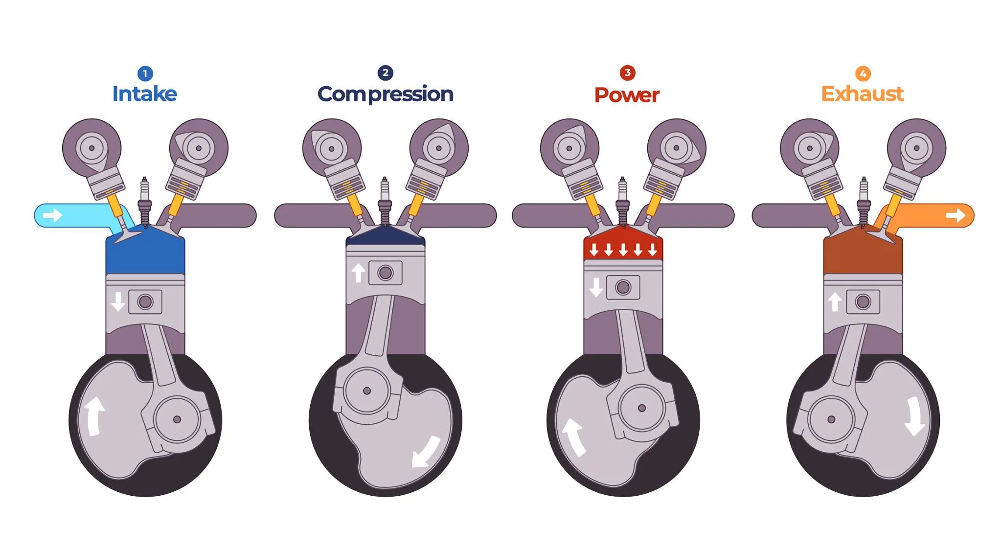
An apprentice may memorize the words Intake, Compression, Power, and Exhaust, but true understanding begins when the apprentice can visualize what the piston, valves, injector, and crankshaft are doing throughout the full 720-degree cycle.
What is happening inside the cylinder during each stroke, and how do all four strokes connect into one complete operating cycle?
Mastering the Four-Stroke Diesel Engine Cycle is a fundamental requirement for anyone developing into a professional technician. By understanding how the engine is supposed to produce power, technicians can logically investigate why an engine may fail to perform correctly.
What Is the Four-Stroke Diesel Engine Cycle?
A four-stroke diesel engine completes four distinct piston strokes for each complete operating cycle.
These four phases are:
- Intake
- Compression
- Power
- Exhaust
Each stroke moves the piston between Top Dead Center and Bottom Dead Center.
A key technical principle to understand is that the Four-Stroke Diesel Engine Cycle requires two complete crankshaft revolutions, or 720 degrees of crankshaft rotation, to complete one power-producing event per cylinder.
The 720-Degree Rule
One complete crankshaft revolution is 360 degrees.
Because one piston stroke requires the piston to travel from the top of the cylinder to the bottom, or from the bottom back to the top, one stroke represents approximately 180 degrees of crankshaft rotation.
Since there are four strokes in the cycle, the total rotation is 720 degrees.
During those 720 degrees:
- the piston moves downward twice
- the piston moves upward twice
- one main power-producing stroke occurs per cylinder
- the camshaft completes one revolution in a conventional four-stroke engine
A simplified sequence looks like this:
- 0° to 180°: Intake
- 180° to 360°: Compression
- 360° to 540°: Power
- 540° to 720°: Exhaust
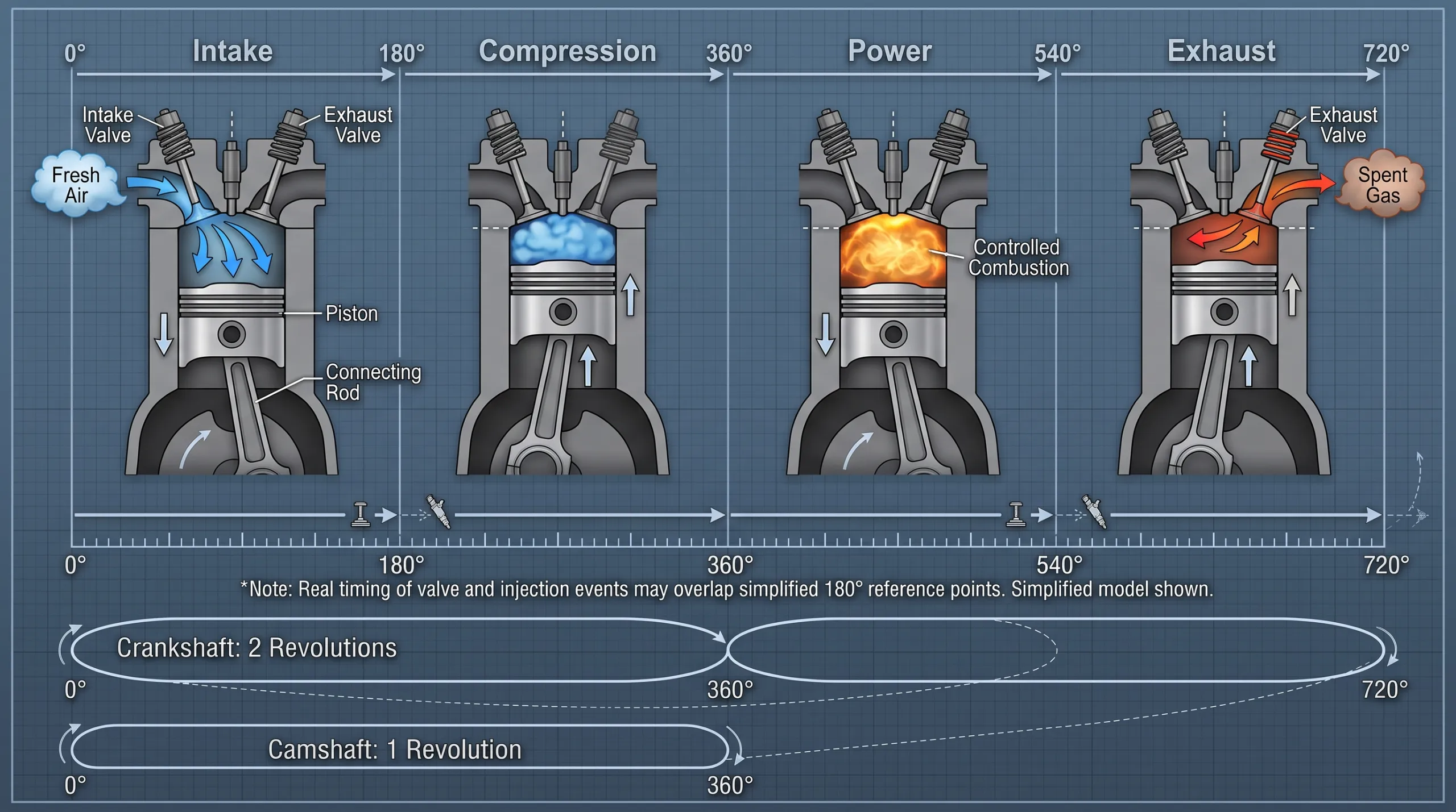
Understanding this 720-degree sequence is central to understanding the Four-Stroke Diesel Engine Cycle.
It is important to remember, however, that real valve and injection events do not necessarily begin and end exactly at these simplified boundaries. Manufacturers adjust timing according to engine design and operating requirements.
TDC and BDC Refresher
To discuss piston position accurately, technicians use two important reference points.
Top Dead Center
Top Dead Center (TDC) is the highest position the piston reaches inside the cylinder.
Bottom Dead Center
Bottom Dead Center (BDC) is the lowest position the piston reaches inside the cylinder.
These positions are important when discussing:
- piston movement
- valve timing
- injection timing
- compression
- engine adjustment procedures
- timing marks
TDC and BDC are reference positions that help technicians describe what is happening throughout the engine cycle.
Stroke 1: Intake
Piston Movement
The piston travels from TDC toward BDC.
Main Valve Condition
The intake valve is open, while the exhaust valve is generally closed during the main intake event.
Main Purpose
The purpose of the intake stroke is to fill the cylinder with fresh air.
As the piston moves downward, pressure conditions within the cylinder allow fresh air to enter through the intake system and open intake valve.
Where turbocharging is fitted, intake manifold pressure may be above atmospheric pressure, allowing a greater mass of air to enter the cylinder.
Efficient cylinder filling helps provide the oxygen needed for later combustion.
This introduces the concept of volumetric efficiency.
Volumetric efficiency describes how effectively the cylinder is filled with fresh charge relative to the engine’s theoretical capacity.
The greater the mass of air entering the cylinder, the more oxygen is potentially available to support combustion during the power-producing part of the cycle.
Stroke 2: Compression
Piston Movement
The piston travels from BDC toward TDC.
Main Valve Condition
Both intake and exhaust valves are closed during the main compression event.
Main Purpose
The purpose of the compression stroke is to compress the trapped air.
As the piston moves upward inside the sealed cylinder, the trapped air is compressed into a much smaller volume.
As the air is compressed:
- its pressure rises
- its temperature rises
This increase in temperature helps prepare the conditions required for compression ignition.
Diesel engines generally use relatively high compression ratios compared with many spark-ignition engines, helping create the conditions necessary for diesel combustion.
What Happens Near the End of Compression?
Fuel injection begins near the end of the compression stroke according to the specific engine design and control strategy.
The injector begins delivering fuel into the cylinder.
The fuel atomizes into fine droplets, begins to vaporize, and mixes with the hot compressed air.
A short ignition delay occurs before combustion begins.
Ignition delay is the short period between the start of injection and the start of combustion.
Injection timing is not identical on every diesel engine. It can vary according to factors such as:
- engine design
- engine speed
- engine load
- temperature
- fuel-system architecture
- electronic control strategy
Stroke 3: Power
Piston Movement
The piston travels from TDC toward BDC.
Main Valve Condition
The valves are generally closed during the main power-producing portion of the stroke.
Main Purpose
The purpose of the power stroke is to convert combustion pressure into piston force and crankshaft torque.
Combustion raises cylinder pressure.
This pressure acts on the piston crown, causing the piston to move downward.
The connecting rod transfers this force to the crankshaft.
The crankshaft then converts the piston and connecting rod movement into rotary motion.
This rotary force is torque.
Useful engine torque depends on several design and operating factors, including:
- cylinder pressure
- crankshaft geometry
- engine displacement
- combustion quality
- engine speed
- air delivery
- fuel delivery
The power stroke is therefore the point where energy released during combustion is converted into useful mechanical output.
Stroke 4: Exhaust
Piston Movement
The piston travels from BDC toward TDC.
Main Valve Condition
The exhaust valve is open during the main exhaust event.
Main Purpose
The purpose of the exhaust stroke is to remove spent combustion gases from the cylinder.
As the piston moves upward, exhaust gases leave the cylinder and enter the exhaust manifold.
Where fitted, some of this exhaust-gas energy can drive the turbocharger turbine.
The engine’s rotating assembly continues turning because of stored rotational energy and because other cylinders in a multi-cylinder engine may be producing power at different points in their cycles.
The piston can therefore complete the exhaust stroke while the crankshaft continues rotating smoothly.
Why Only One Stroke Produces Net Cylinder Power
The power stroke is the main stroke during which combustion pressure performs positive work on the piston.
The other three strokes require energy.
Energy is required to:
- bring fresh air into the cylinder
- compress the trapped air
- remove exhaust gases
In a multi-cylinder engine, the crankshaft continues rotating because different cylinders are positioned at different stages of their cycles.
While one cylinder is compressing air, another may be producing power.
This arrangement helps provide smoother and more continuous engine output.
How the Crankshaft and Camshaft Stay Synchronized
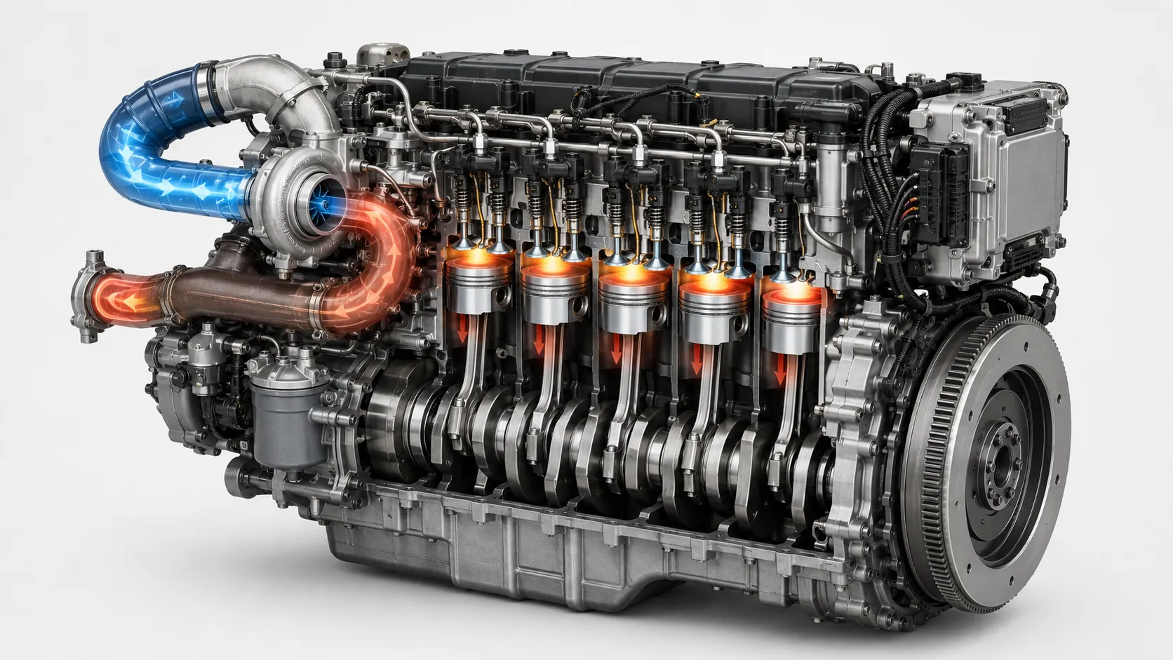
The crankshaft completes two revolutions during one complete Four-Stroke Diesel Engine Cycle.
During the same period, the camshaft completes one revolution.
The camshaft therefore rotates at half crankshaft speed in a conventional four-stroke arrangement.
Depending on engine design, synchronization may be maintained using:
- timing gears
- chains
- belts
- other mechanical drive arrangements
Correct synchronization is necessary for:
- correct valve opening
- correct valve closing
- effective cylinder filling
- proper exhaust flow
- correct engine operation
If the crankshaft and camshaft lose their correct timing relationship, engine performance can be severely affected and mechanical damage may occur on some engine designs.
Valve Timing Is More Complex Than the Textbook Diagram
Beginner diagrams often show:
- the intake valve opening exactly at TDC
- the intake valve closing exactly at BDC
- the exhaust valve opening exactly at BDC
- the exhaust valve closing exactly at TDC
These diagrams are useful for learning the basic sequence.
Real engines, however, may open or close valves before or after these reference positions.
Manufacturers design valve timing to help:
- improve cylinder filling
- improve exhaust flow
- use the momentum of moving gases
- optimize engine performance
Real valve timing adds complexity to the Four-Stroke Diesel Engine Cycle because valve events can extend beyond the simple TDC and BDC boundaries used in beginner diagrams.
This also introduces the concept of valve overlap.
Valve overlap is a period when the intake and exhaust valve events overlap for a short time.
The exact amount and purpose of overlap depend on engine design.
Injection Timing Is Not Simply “At TDC”
A common apprentice misconception is that diesel fuel is always injected exactly when the piston reaches Top Dead Center.
Real injection timing is more complex.
Fuel injection timing is normally described relative to piston position and crankshaft angle.
Injection can begin before or around the top of the compression stroke depending on:
- engine design
- operating conditions
- engine speed
- engine load
- temperature
- fuel-system architecture
- electronic control strategy
TDC is a reference point, not a universal injection command.
On electronically controlled engines, injection timing may be dynamically controlled by the ECM or ECU according to programmed strategies and sensor information.
What Happens in the Other Cylinders?
A multi-cylinder engine does not normally have every cylinder performing the same stroke at the same time.
While one cylinder may be on its power stroke:
- another may be on intake
- another may be compressing
- another may be exhausting
These staggered events help maintain more continuous crankshaft rotation and smoother torque delivery.
Instead of one large power event followed by a long pause, multiple cylinders contribute power at different points during crankshaft rotation.
How Firing Order Fits Into the Cycle
Firing order is the sequence in which the cylinders produce their power strokes.
Firing order helps organize the combustion events of a multi-cylinder engine.
Firing orders are selected to support:
- smooth engine operation
- vibration control
- suitable crankshaft loading
- suitable loading of the engine structure
- consistent power delivery
The exact firing order varies according to engine configuration and manufacturer.
Technicians must therefore use the correct service information for the engine being worked on.
How Turbocharging Interacts With the Four-Stroke Diesel Engine Cycle
Turbocharging connects the exhaust and intake sides of the engine cycle.
During the exhaust stroke, exhaust gas may flow through the turbocharger turbine.
The turbine drives a compressor on the intake side.
During the intake stroke, the compressor can supply pressurized air to the engine.
This allows some energy remaining in the exhaust stream to be used to improve cylinder filling during the next intake process.
The exact turbocharger design and control strategy depend on the engine.
What Happens When One Stroke Is Not Working Correctly?
Thinking about the four individual strokes can help technicians organize diagnostic reasoning.
Intake Problem
An intake-related problem may result in:
- insufficient cylinder filling
- reduced oxygen availability
- poor performance
Possible causes may include:
- restricted air supply
- charge-air leakage
- valve-related breathing problems
Compression Problem
A compression-related problem may result in:
- reduced pressure near the end of compression
- reduced compression temperature
- hard starting
- poor combustion
Possible causes may include:
- worn sealing components
- valve leakage
- mechanical timing problems
Power or Combustion Problem
A combustion-related problem may result in:
- misfire
- low engine output
- abnormal combustion
Possible causes may include:
- incorrect fuel delivery
- injection problems
- insufficient air
- insufficient compression
- timing problems
Exhaust Problem
An exhaust-related problem may cause:
- poor gas evacuation
- increased pumping losses
- reduced performance
Possible causes may include:
- exhaust restrictions
- valve problems
- aftertreatment restrictions where applicable
These examples are not automatic diagnoses.
They simply show how understanding the four strokes can help technicians decide which systems require testing.
Diagnostic Leader Perspective: Identify the Failed Event
Which event in the Four-Stroke Diesel Engine Cycle is no longer happening correctly?
This question can provide structure when approaching an engine-performance problem.
For example, when investigating a misfire, a Diagnostic Leader may ask:
- Did the cylinder receive sufficient air?
- Was compression adequate?
- Was fuel delivered correctly?
- Did combustion occur correctly?
- Were valve events correctly timed?
The Four-Stroke Diesel Engine Cycle gives technicians a structured way to relate symptoms to air movement, compression, combustion, and exhaust flow.
This does not mean every engine fault belongs neatly to one individual stroke.
Engine systems interact with one another across the entire cycle.
The purpose of the four-stroke framework is to make troubleshooting more structured, not to oversimplify diagnosis.
Common Apprentice Mistakes
Mistake 1: “One cycle is one crankshaft revolution.”
Correction: One complete Four-Stroke Diesel Engine Cycle requires two complete crankshaft revolutions, or approximately 720 degrees of crankshaft rotation.
Mistake 2: “Fuel is injected exactly at TDC.”
Correction: Injection timing varies according to engine design and operating conditions. TDC is a reference point, not a universal injection point.
Mistake 3: “Valves only open exactly at TDC and BDC.”
Correction: Real valve events may begin before or end after these reference positions to improve engine breathing and performance.
Mistake 4: “Diesel combustion is an explosion.”
Correction: Diesel combustion is a controlled combustion process in which fuel burns and cylinder pressure rises.
Mistake 5: “All cylinders are doing the same stroke together.”
Correction: In normal multi-cylinder engines, cylinders are positioned at different points in their cycles so that power events occur at different times.
Frequently Asked Questions About the Four-Stroke Diesel Engine Cycle
What is the Four-Stroke Diesel Engine Cycle?
The Four-Stroke Diesel Engine Cycle is the operating sequence used by a four-stroke diesel engine to convert fuel energy into mechanical work through the intake, compression, power, and exhaust strokes.
What are the four strokes?
The four strokes are:
Intake → Compression → Power → Exhaust
Why does a four-stroke engine require 720 degrees?
Each stroke involves approximately 180 degrees of crankshaft rotation.
Four strokes therefore require approximately:
180° × 4 = 720°
This equals two complete crankshaft revolutions.
What is TDC?
Top Dead Center is the highest position the piston reaches inside the cylinder.
What is BDC?
Bottom Dead Center is the lowest position the piston reaches inside the cylinder.
When is diesel fuel injected?
Fuel is generally injected near the end of the compression stroke.
Exact injection timing depends on engine design and operating conditions.
Which stroke produces power?
The power stroke is the main stroke during which combustion pressure performs positive work on the piston and creates useful crankshaft torque.
Why does the camshaft rotate at half crankshaft speed?
In a conventional four-stroke engine, the crankshaft rotates twice during one complete cycle while the camshaft only needs to complete one revolution to operate the valves through that same cycle.
What is valve overlap?
Valve overlap is a short period when the intake and exhaust valve events overlap.
The exact timing and amount of overlap depend on engine design.
Do all cylinders complete the same stroke at the same time?
No.
In a multi-cylinder engine, the cylinders are normally at different stages of their cycles according to the engine’s firing order and mechanical configuration.
This helps provide smoother and more continuous engine output.
Final Message: Visualize the 720-Degree Cycle
The simplified four-stroke sequence can be represented as:
- 0°–180°: Intake
- 180°–360°: Compression
- 360°–540°: Power
- 540°–720°: Exhaust
This is a teaching model.
Actual valve and injection events may extend across these simplified boundaries depending on engine design.
A technician who can visualize piston position, valve events, airflow, fuel injection, combustion, and crankshaft rotation throughout the full 720-degree Four-Stroke Diesel Engine Cycle has moved beyond simply memorizing four words.
Mastering the Four-Stroke Diesel Engine Cycle gives technicians the foundation required to understand how normal combustion events relate to engine-performance problems.
When a fault appears, ask:
What should be happening at this point in the cycle, and what evidence shows that it is not happening correctly?
That is systems thinking.
That is the beginning of becoming a Diagnostic Leader.
References and Further Reading
For engine-specific valve timing, injection timing, operating limits, and adjustment procedures, technicians should always consult the appropriate manufacturer technical information for the engine being worked on.
Useful technical source categories include:
- engine manufacturer technical literature
- OEM service and training information
- OEM Operation and Maintenance Manuals
- SAE International technical resources
- recognized engineering education references
Modern Trade Skills Institutional Reference
Modern Trade Skills Handbook Version 1.0
Institutional reference for the Modern Trade Skills Diagnostic Leader philosophy, systems-thinking framework, and technician-development principles.