
Monday to Saturday - 8:00 -17:30

A diesel engine may have clean fuel, correct injection timing, and healthy compression, but it still cannot produce expected power if it does not receive enough clean air. How does air travel from the atmosphere all the way into the cylinder, and what role does the turbocharger play in that journey?
The Diesel Engine Air Intake system is responsible for capturing, cleaning, compressing, and cooling the air before it reaches the combustion chamber.
This guide explains how heavy equipment breathes, how turbochargers recover exhaust energy, and why understanding the complete air path is essential for accurate troubleshooting.
Why Diesel Engines Need Clean, Dense Air
Diesel combustion requires oxygen. A well-designed Diesel Engine Air Intake system helps deliver the clean air mass the engine needs across different loads and operating conditions.
More usable air mass generally means more oxygen is available for combustion, allowing the engine to support the required fuel delivery within its designed operating limits.
To understand how an engine breathes, a technician must recognize the difference between air volume, air density, and air mass.
- Air Volume: The physical space occupied by the air.
- Air Density: How much air mass is contained within a given volume.
- Air Mass: The actual mass of air delivered to the engine. Because air contains oxygen, increasing air mass generally increases the oxygen available for combustion.
Air requirements vary according to:
- engine design
- engine speed
- engine load
- altitude
- ambient conditions
- control strategy
Providing sufficient air mass helps the engine support the required fuel delivery and combustion under load while remaining within its designed operating limits.
The Diesel Engine Air Intake Path
Understanding the physical sequence of components is the first step in diagnosing airflow problems.
A typical path is:
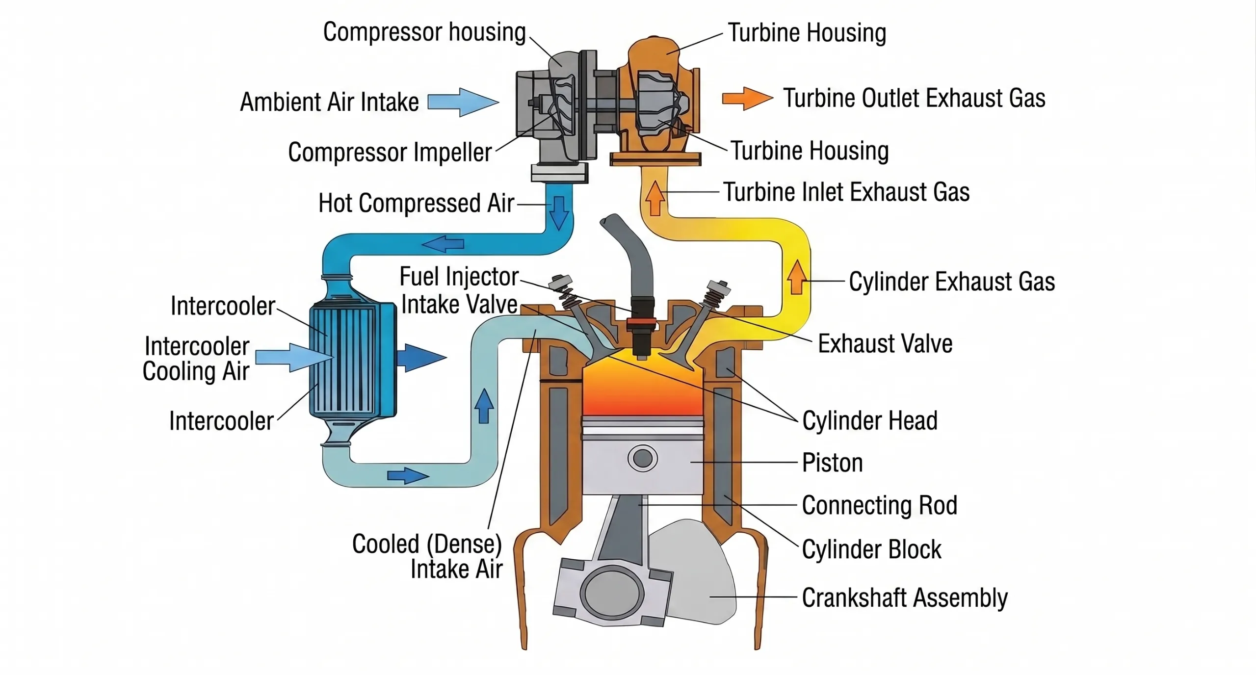
Atmosphere → Pre-Cleaner, where fitted → Air Cleaner → Intake Ducting → Turbocharger Compressor → Charge-Air Cooler, where fitted → Intake Manifold → Intake Valve → Cylinder
Every section of the Diesel Engine Air Intake path must remain:
- clean
- sealed
- correctly assembled
- free from excessive restriction
A problem at any point can affect the amount or quality of air reaching the engine.
Air Cleaners and Pre-Cleaners
The air-cleaning system provides the first line of protection against dirt and debris.
Pre-Cleaner
Where fitted, a pre-cleaner may remove larger dust particles and debris before air reaches the primary filter.
Possible designs include:
- centrifugal pre-cleaners
- dust ejectors
- other manufacturer-specific systems
Primary Air Filter
The primary filter removes fine contamination from incoming air before it reaches sensitive engine components.
Safety or Secondary Element
Where fitted, a secondary element provides an additional layer of engine protection.
The exact arrangement varies by machine and manufacturer.
Technicians should always follow OEM procedures and restriction criteria when inspecting, servicing, or replacing air-cleaner elements.
Intake Ducting: The Sealed Path to the Turbocharger
Hoses, clamps, boots, pipes, and ducting connect the air cleaner to the turbocharger.
These components must remain sealed and structurally sound.
Possible problems include:
- loose clamps
- split hoses
- damaged boots
- collapsed ducting
- incorrectly fitted connections
- damaged sealing surfaces
A leak before the turbocharger can allow unfiltered air to enter the system.
A restriction before the turbocharger can reduce airflow reaching the compressor and affect engine performance. Because of this, the condition of the Diesel Engine Air Intake ducting directly affects both airflow and contamination control.
This is why intake ducting should never be treated as simple plumbing.
It is part of the engine’s contamination-control and airflow system.
How a Turbocharger Works
A turbocharger is an energy-recovery and air-compression device.
It uses energy from the engine’s exhaust gases to drive a compressor that increases the air mass supplied to the engine. In a turbocharged engine, the turbocharger is a central part of the Diesel Engine Air Intake system because it increases the air mass delivered toward the cylinders.
The turbocharger has two connected sides.
Turbine Side
Exhaust gas flows through the turbine housing and turns the turbine wheel.
Compressor Side
The turbine wheel is connected by a shaft to the compressor wheel.
As the turbine turns, the compressor wheel also rotates and compresses incoming air.
The basic relationship is:
Exhaust Energy → Turbine Rotation → Shaft Rotation → Compressor Rotation → Increased Intake Air Mass
The turbocharger does not create energy from nothing.
It recovers part of the energy in the exhaust stream and uses it to improve the engine’s air supply.
The Main Parts of a Turbocharger
Exact turbocharger construction varies, but common components include:
- compressor housing
- compressor wheel
- center housing or bearing section
- shaft
- turbine wheel
- turbine housing
- lubrication supply
- oil drain
- wastegate or actuator components where fitted
Compressor Housing
The compressor housing directs incoming and compressed air around the compressor wheel.
Compressor Wheel
The compressor wheel draws in air and increases its pressure and air mass.
Center Housing and Bearing Section
The center section supports the rotating shaft and bearings.
Shaft
The shaft connects the turbine wheel to the compressor wheel.
Turbine Wheel
The turbine wheel is driven by exhaust gas.
Turbine Housing
The turbine housing directs exhaust gas toward and away from the turbine wheel.
Lubrication Supply and Drain
Engine oil is commonly used to lubricate and help cool the turbocharger bearing system.
Correct oil supply and unrestricted oil drainage are therefore important to turbocharger reliability.
Why Compressing Air Makes It Hotter
Compressing a gas raises its temperature.
This means the air leaving the turbocharger compressor is generally hotter than the air entering it.
Hotter air is less dense than cooler air at the same pressure.
Because air density affects how much air mass can occupy a given volume, this heating reduces some of the density benefit gained through compression.
This is why many turbocharged engines use some form of charge-air cooling.
What the Charge-Air Cooler Does
The Charge-Air Cooler, commonly called a CAC or aftercooler, removes heat from the compressed air before it enters the engine.
The general sequence is:
Turbocharger Compressor → Hot Compressed Air → Charge-Air Cooler → Cooler, Denser Air → Intake Manifold
Cooling the compressed air increases its density, allowing a greater air mass to occupy a given volume under suitable operating conditions.
The charge-air cooler is therefore an important part of the Diesel Engine Air Intake architecture.
Designs vary and may include:
- air-to-air charge cooling
- liquid-cooled aftercooling
- other manufacturer-specific arrangements
Not every engine uses the same type of cooling system.
Intake Manifold and Air Distribution
The intake manifold distributes the incoming air toward the cylinders.
Manifold design influences:
- pressure distribution
- cylinder filling
- air movement
- intake-valve supply
The goal is to provide suitable airflow to each cylinder according to the engine’s design.
The exact flow pattern varies between engines.
Fixed-Geometry Turbochargers
A fixed-geometry turbocharger has a turbine housing with fixed internal geometry.
Possible advantages include:
- simpler construction
- fewer moving control components
A fixed design must provide an acceptable compromise across different operating conditions.
Its response at low engine speed and its flow capability at higher engine speed depend on the design selected by the manufacturer.
Wastegated Turbochargers
A wastegate allows some exhaust gas to bypass the turbine wheel.
Its purpose is to help control turbocharger speed and intake boost within the engine’s designed operating strategy.
Wastegate systems may be:
- pneumatic
- mechanical
- electronic
- manufacturer-specific
Wastegated turbochargers are used in a range of engine applications and are not limited to one particular engine generation.
Variable-Geometry Turbochargers
Variable-geometry turbochargers, commonly called VGT or VNT systems, change the effective turbine flow area to influence turbocharger response across different operating conditions.
At some lower-flow conditions, the geometry may be adjusted to increase turbine response.
At higher-flow conditions, the geometry may change to manage exhaust flow and backpressure.
Depending on engine design, VGT systems may also support:
- emissions-control strategies
- EGR flow management
- engine braking
- other manufacturer-specific functions
VGT is not universal.
The exact design and control strategy depend on the engine manufacturer and application.
Multi-Stage and Multiple Turbocharger Systems
Some diesel engines use more than one turbocharger.
Possible arrangements include:
- two-stage systems
- series turbochargers
- parallel turbochargers
- other multi-turbo configurations
These systems may be used to achieve:
- a broader operating range
- increased airflow capability
- improved response
- higher power density
The exact arrangement depends on the performance requirements of the engine.
How Airflow Changes With Engine Load
Consider an excavator entering a hard dig or a loader driving into a pile.
As the machine load increases:
- engine load rises
- fuel demand may increase
- combustion energy may increase
- exhaust energy may increase
- turbocharger response may increase
- boost and air mass may rise
The air and fuel systems must remain appropriately matched within the engine-control strategy.
Useful engine output depends on the complete system, including:
- airflow
- fuel delivery
- combustion
- engine speed
- operating temperature
- control strategy
- machine load
More boost by itself does not automatically mean more useful power.
Sensors Used in Modern Air-Management Systems
Electronically controlled engines may use several sensors to monitor the Diesel Engine Air Intake system.
Not every engine uses every sensor listed below.
Manifold Absolute Pressure Sensor
A MAP sensor measures absolute pressure in the intake manifold.
Depending on the diagnostic system, this information can be compared with atmospheric pressure to help determine boost conditions.
Intake Air Temperature Sensor
An IAT sensor measures intake-air temperature.
The engine-control system may use this information for:
- airflow calculations
- fueling strategies
- engine protection
- other control functions
Barometric Pressure Sensor
A barometric sensor provides atmospheric-pressure information.
This can help the control system account for changing altitude and environmental conditions.
Turbocharger Speed Sensor
Where fitted, a turbocharger speed sensor provides information about turbocharger shaft speed.
Mass Airflow Sensor
Where fitted, a mass airflow sensor measures the mass of incoming air.
The exact sensor architecture depends on the engine and manufacturer.
ECM and ECU Control of Turbocharging
Electronically controlled engines may use sensor data to manage turbocharger-related functions.
Possible inputs include:
- engine speed
- engine load
- manifold pressure
- intake temperature
- atmospheric pressure
- emissions-system conditions
Possible outputs include:
- VGT actuator commands
- wastegate control
- fuel adjustments
- protection strategies
The control system coordinates airflow, fuel delivery, engine protection, and other functions according to the manufacturer’s strategy.
Control logic can vary significantly between engines.
Restrictions and Leaks: Two Different Problems
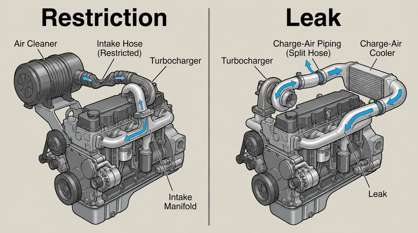
One of the most useful distinctions in air-system diagnosis is understanding the difference between a restriction and a leak.
Restriction
A restriction reduces the amount of air that can pass through the system.
Possible examples include:
- restricted air filter
- blocked inlet
- damaged ducting
- internal hose collapse
Leak
A leak allows air to escape or contamination to enter depending on where the leak occurs.
A leak before the turbocharger may allow unfiltered air to enter.
A leak after the turbocharger may allow compressed air to escape before reaching the engine.
When troubleshooting the Diesel Engine Air Intake, ask:
Is the system restricted, or is the system leaking?
This question can help organize the next stage of testing.
How a Charge-Air Leak Can Cause Low Power
The turbocharger compresses air, which should then travel through the charge-air cooler and toward the intake manifold.
A split hose, loose connection, damaged seal, or leaking CAC can allow compressed air to escape.
When this happens, less air mass may reach the cylinders.
Possible effects can include:
- reduced engine performance
- lower-than-expected boost
- abnormal exhaust smoke
- increased exhaust temperature
- changes in engine-control behavior
The exact symptoms depend on engine design, control strategy, operating load, and the severity of the leak.
Chief Engineer’s Diagnostic Case: Low Power Without a Failed Turbocharger
A wheel loader was reported to have poor power under load and evidence of low boost.
A parts-changing approach could have immediately blamed the turbocharger.
Instead, the complete charge-air system was tested.
Using appropriate regulated testing methods and following safe procedures, the fault was traced to the charge-air cooler circuit.
Testing showed that the turbocharger itself was not the root cause.
Compressed air was escaping through the charge-air system before reaching the engine.
After the leak was repaired and the system was validated, machine performance was restored.
The lesson was simple:
The symptom suggested low engine power.
The turbocharger was not the root cause.
The complete air system had to be tested.
Pressure testing must always follow OEM procedures, use correct tooling, and remain within safe pressure limits.
Diagnostic Leader Perspective: Test the Complete Air System
When investigating an airflow-related complaint, ask:
- Is the engine receiving clean air?
- Is there excessive restriction?
- Is the turbocharger producing airflow?
- Is compressed air reaching the intake manifold?
- Is the charge-air cooler leaking?
- Are the sensors reporting believable information?
- Is the turbocharger control system responding correctly?
- Are exhaust conditions providing suitable turbine drive?
- Are turbocharger lubrication and drainage conditions correct?
Do not condemn the turbocharger until the complete intake, charge-air, exhaust-drive, control, and lubrication conditions relevant to the complaint have been evaluated.
That is a systems-based diagnostic approach.
Common Air-Intake and Turbocharging Problems
Air and turbocharging systems can develop many different faults.
Examples include:
- restricted air filter
- damaged pre-cleaner
- split intake hose
- loose clamp
- charge-air leak
- damaged charge-air cooler
- turbocharger mechanical damage
- turbocharger lubrication problem
- actuator fault
- wastegate fault
- sensor fault
- wiring problem
- exhaust-side problem reducing turbine drive
This list identifies possible problem areas.
It is not a diagnostic flowchart.
Testing is still required to identify the root cause.
Common Apprentice Mistakes
Mistake 1: “Low boost means the turbocharger is bad.”
Correction: Low boost can result from intake restrictions, charge-air leaks, exhaust-side problems, control faults, sensor issues, or an actual turbocharger problem.
Mistake 2: “A clean-looking air filter must be good.”
Correction: Visual inspection is not enough. Air-filter condition should be evaluated according to OEM inspection, replacement, and restriction criteria.
Mistake 3: “More boost always means more power.”
Correction: Engine output depends on the complete air, fuel, combustion, and control system.
Mistake 4: “Oil in the intake automatically means turbo failure.”
Correction: Oil presence must be evaluated in context. Crankcase ventilation, operating conditions, engine wear, and turbocharger condition may all influence oil found in intake plumbing.
Mistake 5: “Black smoke always means bad injectors.”
Correction: Black smoke can have several causes, including air-system restrictions, charge-air leaks, fueling problems, and other combustion-related conditions.
Frequently Asked Questions About Diesel Engine Air Intake
What is the purpose of the diesel engine air-intake system?
The Diesel Engine Air Intake system captures and cleans incoming air and, where applicable, compresses and cools it before it reaches the cylinders.
What does a turbocharger do?
A turbocharger uses energy from the exhaust gases to drive a compressor that increases the air mass supplied to the engine.
Why does compressed air become hot?
Compressing a gas raises its temperature.
This is why turbocharged engines commonly use charge-air cooling.
What does a charge-air cooler do?
A charge-air cooler removes heat from compressed intake air.
Cooling increases air density and can allow a greater air mass to reach the engine.
What is boost pressure?
Boost refers to intake-manifold pressure above atmospheric pressure.
Diagnostic systems may display pressure in different ways, so technicians must understand whether the value being viewed is absolute or gauge pressure.
Does low boost always mean a failed turbocharger?
No.
Low boost can result from intake restrictions, charge-air leaks, exhaust-side problems, control faults, sensor issues, or an actual turbocharger problem.
What is a wastegate?
A wastegate allows some exhaust gas to bypass the turbine wheel to help regulate turbine drive and control boost under applicable operating conditions.
What is a variable-geometry turbocharger?
A variable-geometry turbocharger changes the effective turbine flow area to influence turbocharger response across different engine operating conditions.
Can an air leak cause low engine power?
Yes.
If compressed air escapes through the charge-air system before reaching the engine, the available air mass can decrease and engine performance may be affected.
Why is clean intake air important?
Clean intake air protects the turbocharger and engine from abrasive contamination.
A sealed Diesel Engine Air Intake system helps prevent dirt from entering and causing wear to the turbocharger and internal engine components.
Final Message: Follow the Air
To understand the Diesel Engine Air Intake, visualize the complete path:
Atmosphere → Air Cleaner → Intake Ducting → Turbocharger Compressor → Charge-Air Cooler → Intake Manifold → Cylinder
Then understand the exhaust-side connection:
Cylinder → Exhaust Manifold → Turbocharger Turbine
When an engine develops a low-power or airflow-related complaint, do not jump immediately to replacing the turbocharger or fuel-system components.
Follow the air.
Ask:
- Where should the air be?
- Is the path restricted?
- Is the path leaking?
- Is the turbocharger responding?
- Are the sensors believable?
- Is compressed air actually reaching the engine?
- Is the engine receiving the air mass it needs?
That is systems thinking.
That is the beginning of becoming a Diagnostic Leader. Understanding the Diesel Engine Air Intake as one complete system makes airflow-related problems much easier to investigate logically.
References and Further Reading
For engine-specific air-filter restrictions, turbocharger control strategies, charge-air system specifications, testing procedures, and operating limits, technicians should consult the appropriate manufacturer technical information.
Useful technical source categories include:
- OEM Operation and Maintenance Manuals
- Cummins and Caterpillar technical literature
- Garrett Motion and BorgWarner turbocharger technical resources
- SAE International technical resources
- OEM service and training information where publicly available
Modern Trade Skills Institutional Reference
Modern Trade Skills Handbook Version 1.0
Institutional reference for the Modern Trade Skills Diagnostic Leader philosophy, systems-thinking framework, and technician-development principles.