
Monday to Saturday - 8:00 -17:30

Modern diesel engines are no longer controlled only by gears, springs, mechanical governors, and fuel pumps.
Today, Diesel Engine Electrical Systems form an essential part of engine operation.
Electrical power supplies the control modules. Sensors report what is happening inside and around the engine. The Engine Control Module processes that information. Actuators respond to electrical commands. Communication networks allow the engine to exchange information with the transmission, hydraulic system, aftertreatment system, and other machine controllers.
For technicians, this means electrical knowledge is no longer separate from mechanical knowledge.
To understand a modern diesel engine, you must understand both.
The easiest way to make the system logical is to follow the electrical control path:
Power Supply → Power Distribution → ECM → Sensors → Software Logic → Actuators → Engine Response
Once this sequence is understood, Diesel Engine Electrical Systems stop looking like a collection of confusing wires and begin to look like one connected control system.
From Mechanical Engines to Electronic Control
Older diesel engines relied heavily on mechanical systems.
Fuel injection timing, engine speed, fuel quantity, and shutdown functions could be controlled mechanically.
Modern engines use electronic control because it allows the engine to respond more precisely to changing operating conditions.
Electronic control can support:
- accurate fuel delivery
- engine protection
- emissions control
- improved load response
- diagnostic fault monitoring
- communication with other machine systems
The result is an engine that continuously measures conditions, makes decisions, and adjusts its operation.
This is the foundation of Diesel Engine Electrical Systems.
The Big Picture: How Diesel Engine Electrical Systems Work
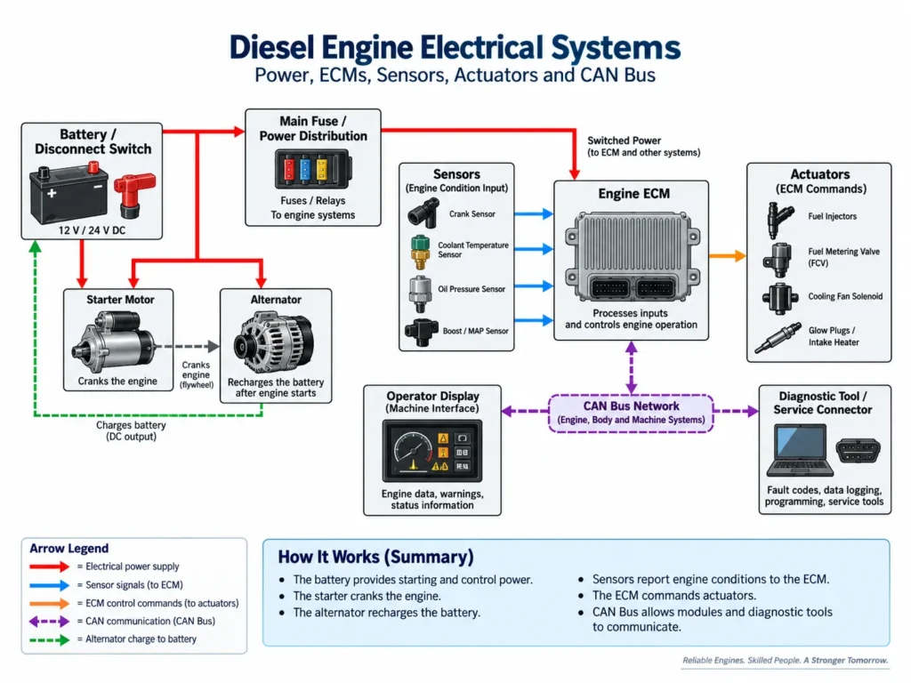
A modern electronically controlled diesel engine can be understood through seven basic stages.
1. Power Supply
Batteries provide electrical energy for starting and for engine control systems when the engine is not running.
2. Power Distribution
Fuses, relays, circuit breakers, wiring, and distribution modules route electrical power to the required components.
3. Engine Control Module
The ECM receives electrical power and becomes the main decision-making controller for the engine.
4. Sensors
Sensors measure physical conditions such as:
- temperature
- pressure
- speed
- position
They convert those conditions into electrical signals.
5. Software Logic
The ECM compares sensor information with programmed operating strategies.
6. Actuators
The ECM sends electrical commands to devices such as injectors, valves, and control actuators.
7. Engine Response
The engine responds by changing fuel delivery, boost control, speed, cooling demand, emissions operation, or another controlled function.
This complete loop is the heart of Diesel Engine Electrical Systems.
Electrical Power Supply
Everything begins with electrical power.
If the power supply is unstable, the rest of the control system may also become unstable.
Heavy equipment commonly uses battery systems designed to provide the current required for engine starting and electronic control.
The exact voltage and battery arrangement depend on the machine.
Important components may include:
- batteries
- battery cables
- master disconnect switches
- main fuses
- circuit breakers
- relays
- power distribution modules
- ground cables
Technicians should remember one important rule:
An electronic control module cannot make reliable decisions if its power supply is unreliable.
Low voltage, excessive voltage drop, loose battery connections, poor grounds, and charging-system problems can create symptoms that look like failed sensors or failed control modules.
Fuses, Relays and Power Distribution
Fuses and circuit breakers protect electrical circuits from excessive current.
Relays allow a relatively low-current control circuit to switch a higher-current load.
Power distribution modules may combine several fuses, relays, and electrical connections into one protected assembly.
When a fuse opens repeatedly, replacing the fuse is not the complete repair.
The technician should determine why excessive current is flowing.
Possible causes may include:
- shorted wiring
- damaged insulation
- failed electrical loads
- incorrect repairs
- contamination inside connectors
- wiring contacting the machine structure
A blown fuse is therefore usually a symptom that requires diagnosis.
Starting Systems
The starting system must rotate the diesel engine fast enough for combustion to begin.
A typical starting circuit may include:
Battery → Key or Start Command → Controller / Interlock Logic → Starter Relay → Starter Solenoid → Starter Motor
The exact control sequence varies between machines.
Some systems may confirm conditions such as:
- transmission neutral
- machine safety interlocks
- engine status
- start authorization
before allowing the starter circuit to operate.
The starter solenoid performs two important jobs.
It engages the starter drive with the engine flywheel and closes the high-current circuit that powers the starter motor.
Because starter circuits carry high current, resistance in battery cables, terminals, connections, or ground paths can create major starting problems.
This is why voltage-drop testing is so important when diagnosing slow cranking.
Charging Systems
Once the engine is running, the charging system supplies electrical power and replenishes the batteries.
The alternator converts mechanical rotation into electrical energy.
Internal rectification converts the generated alternating current into direct current for the machine electrical system.
A voltage regulator controls charging output.
Charging-system problems can affect much more than the batteries.
An unstable charging system may interfere with:
- ECM operation
- sensor signals
- communication networks
- actuators
- electronic displays
- other machine controllers
When investigating unexplained electrical faults, technicians should not forget the charging system.
The Engine Control Module
The Engine Control Module is the central controller for many engine functions.
Depending on the engine, the ECM may control or supervise:
- engine speed
- fuel injection
- injection timing
- fuel pressure
- turbocharger control
- EGR operation
- cooling strategies
- engine protection
- aftertreatment functions
- diagnostic fault monitoring
The ECM receives information from sensors, processes that information using programmed logic, and sends commands to actuators.
In Diesel Engine Electrical Systems, the ECM should not be viewed as a mysterious black box.
Think of it as a controller performing three basic jobs:
Receive → Decide → Command
Sensors provide information.
Software evaluates it.
Actuators carry out the command.
Sensors: The Eyes and Ears of the ECM
Sensors allow the ECM to know what is happening inside the engine.
Without sensors, the ECM would have no reliable information about operating conditions.
Common sensor types include:
Temperature Sensors
Used for conditions such as:
- coolant temperature
- intake-air temperature
- fuel temperature
- oil temperature
- exhaust temperature
Many temperature sensors change resistance as temperature changes.
Pressure Sensors
Used for measurements such as:
- boost pressure
- oil pressure
- fuel rail pressure
- atmospheric pressure
Many pressure sensors use a reference voltage, ground, and signal circuit.
Position Sensors
Used to report component position.
Examples can include:
- accelerator pedal position
- EGR valve position
- throttle position
- actuator position
Speed and Timing Sensors
Crankshaft and camshaft sensors help the ECM determine engine speed and rotational position.
Sensor design varies.
Some systems use magnetic sensors while others use Hall-effect or other electronic sensing methods.
The technician must identify the correct sensor type before testing it.
Reference Voltage Circuits
Many electronic sensors operate using a regulated reference voltage supplied by the ECM.
A typical sensor circuit may contain:
- reference voltage
- sensor ground
- signal return
One of the most important lessons in Diesel Engine Electrical Systems is that several sensors may share the same reference or ground circuit.
This creates an important diagnostic situation.
Suppose the ECM suddenly logs faults for:
- boost pressure
- oil pressure
- fuel pressure
- another pressure sensor
A parts changer may assume that four sensors failed at the same time.
A Diagnostic Leader asks:
What electrical path do these sensors share?
One shorted sensor or damaged shared circuit may pull down the reference voltage and create several fault codes at once.
Actuators: Turning Electrical Commands Into Physical Action
Sensors report conditions.
Actuators change conditions.
An actuator receives an electrical command and converts it into mechanical action.
Examples include:
- fuel injectors
- fuel-control valves
- EGR valves
- turbocharger actuators
- cooling-fan controls
- shutdown solenoids
- DEF dosing components
Depending on the design, the ECM may control an actuator using:
- switched voltage
- switched ground
- current control
- pulse width modulation
- digital communication
The correct testing method therefore depends on the actuator and circuit design.
Pulse Width Modulation
Pulse Width Modulation, or PWM, is commonly used to control actuators.
Instead of simply switching a device fully ON or OFF, the controller rapidly switches the circuit.
By changing the percentage of time that the circuit is energized, the ECM can vary the energy delivered to the actuator.
This percentage is called the duty cycle.
PWM control may be used for devices such as:
- control valves
- fan systems
- EGR actuators
- fuel-control components
A technician should avoid assuming that a PWM-controlled circuit behaves exactly like a steady DC voltage.
Waveform, duty cycle, frequency, current, and circuit design may all matter.
Fuel-System Electronics
Modern electronically controlled fuel systems depend heavily on electrical signals.
The ECM may monitor:
- engine speed
- crankshaft position
- accelerator demand
- fuel pressure
- boost pressure
- temperature
- engine load
It then determines how the fuel system should respond.
Depending on the engine design, the ECM may control:
- injector timing
- injection duration
- fuel-pressure control
- multiple injection events
- fuel metering
This makes the fuel system a good example of mechanical and electrical systems working together.
A fuel-pressure problem may be hydraulic, mechanical, electrical, or a combination of these.
That is why Diesel Engine Electrical Systems must be understood as part of the complete engine.
Air-Management Electronics
Modern engines also use electronic control to manage airflow.
Depending on the engine, the ECM may control:
- variable-geometry turbocharger operation
- wastegate operation
- EGR flow
- intake throttling
- boost protection
The ECM uses sensor information to determine whether commanded airflow and actual airflow agree.
If they do not agree, the technician must determine whether the problem is:
- electrical
- mechanical
- pneumatic
- related to airflow restriction
- related to an actuator
- related to sensor information
A fault code may identify the disagreement, but not necessarily the root cause.
Emissions Electronics
Tier 4 Final and Stage V engines depend heavily on electronic control.
Aftertreatment systems may use:
- exhaust temperature sensors
- differential-pressure sensors
- NOx sensors
- DEF system sensors
- dosing controls
- regeneration logic
For example, the ECM may use differential-pressure information and other operating data to evaluate DPF loading.
During regeneration, soot is oxidized and reduced.
Regeneration does not convert soot into ash.
Ash is non-combustible residue that remains in the DPF and accumulates over time.
Emissions control therefore adds another layer to Diesel Engine Electrical Systems, but the diagnostic principles remain the same:
Power → Ground → Signal → Logic → Command → Response
Wiring Harness Architecture
The wiring harness is the physical pathway that connects the electrical system.
It carries:
- battery power
- ground circuits
- sensor references
- sensor signals
- actuator commands
- communication data
Harnesses may include:
- main trunk sections
- smaller branch circuits
- shielded wiring
- twisted communication pairs
- sealed connectors
- protective conduit
- heat protection
The engine environment is difficult for electrical wiring.
Harnesses must survive:
- vibration
- heat
- oil
- dust
- moisture
- movement
- abrasion
A damaged harness can create intermittent faults that are far more difficult to diagnose than a completely failed component.
Ground Circuits and Return Paths
Every electrical circuit requires a complete return path.
Poor grounds are responsible for many difficult electrical problems.
A high-resistance ground can affect:
- starter performance
- charging
- ECM supply voltage
- sensor accuracy
- communication networks
- actuator operation
A ground connection can look clean externally and still have excessive resistance.
That is why visual inspection alone is not enough.
Loaded voltage-drop testing is often more useful than a simple continuity test because it tests the circuit while current is actually flowing.
For Diesel Engine Electrical Systems, good grounds are just as important as good power supplies.
CAN Bus and J1939 Communication
Modern heavy equipment contains several electronic control modules.
The engine, transmission, hydraulic system, display, aftertreatment system, and other controllers may need to exchange information.
CAN communication allows controllers to share information without requiring a separate dedicated wire for every piece of data.
J1939 is a communication standard widely used in heavy-duty vehicles and equipment.
A typical CAN network uses two communication conductors:
- CAN High
- CAN Low
The wires are normally arranged as a twisted pair to help protect the signal from electrical interference.
The Engine ECM may broadcast information such as:
- engine speed
- torque
- temperatures
- fault information
Other controllers can use that information for their own functions.
This means a communication failure can sometimes create symptoms across several machine systems simultaneously.
Understanding Electrical Signals
A Diagnostic Leader must understand what type of electrical signal is being tested.
Analog Signals
Analog signals vary continuously.
They may be used to represent changing conditions such as pressure or position.
Digital Signals
Digital signals switch between defined electrical states.
They may be used for switching, position sensing, timing, or communication.
PWM Signals
PWM signals control devices by changing duty cycle.
Frequency Signals
Some sensors communicate speed by producing pulses whose frequency changes with rotational speed.
The correct meter setting, test procedure, and diagnostic tool depend on the signal type.
How the ECM Makes Decisions
Consider a simplified example.
The operator requests more engine power.
The ECM receives information from several sources:
- accelerator demand
- engine speed
- boost pressure
- fuel pressure
- temperature
- protection systems
The ECM validates the inputs.
It then compares those inputs with its programmed control strategy.
If conditions allow, it may command:
- increased fuel delivery
- a turbocharger actuator change
- altered fuel pressure
- another engine-control response
Sensors then report the result.
The ECM compares commanded operation with actual operation and continues adjusting.
This closed-loop process happens continuously while the engine operates.
That is the real architecture behind Diesel Engine Electrical Systems.
Common Electrical Failure Modes
Electrical faults often come from the physical environment rather than from electronic complexity itself.
Common problems include:
Open Circuits
A wire, terminal, or connection becomes electrically disconnected.
Short to Ground
A powered or signal wire contacts ground.
Short to Power
A circuit receives voltage from another circuit that it should not receive.
High Resistance
Corrosion, poor terminals, loose connections, or damaged wiring restrict current flow.
Connector Problems
Moisture, contamination, damaged seals, loose terminals, or vibration may affect electrical contact.
Harness Chafing
A harness rubs against a bracket, engine component, or frame until insulation is damaged.
Shared Circuit Faults
A problem in a common power, ground, or reference circuit may affect several components at once.
Diagnostic Leader Perspective: Test the Circuit, Not Just the Component
A fault code is the beginning of diagnosis.
It is not proof that the named component has failed.
When testing Diesel Engine Electrical Systems, ask:
Does the component have the correct power supply?
Do not assume power is present simply because a fuse looks good.
Does it have a reliable ground?
Test the ground under load when appropriate.
Is the reference voltage correct?
A shared reference fault may affect several sensors.
Is the signal plausible?
Compare the signal with actual machine conditions and other related data.
Is the wiring intact?
Inspect and test connectors, terminals, harness routing, and circuit resistance where appropriate.
Is the ECM commanding the component?
A good actuator cannot respond to a command that is not present.
Did the component respond correctly?
Command and response must agree.
This diagnostic sequence helps separate:
input problems → control problems → output problems → mechanical response problems
A Fault Code Is a Clue, Not a Diagnosis
Consider five sensors reporting faults at the same time.
Replacing five sensors would be expensive and unlikely to solve a shared electrical problem.
A better approach is to inspect the schematic.
You may discover that all five sensors share:
- the same reference circuit
- the same ground
- the same power supply
- the same connector
- the same harness section
One circuit problem can therefore create several fault codes.
This is systems thinking.
What This Means for Technicians
Understanding Diesel Engine Electrical Systems changes how technicians approach modern engine faults.
Electrical diagnosis is not about randomly checking wires.
It is about understanding the architecture.
A technician should be able to identify:
- where power comes from
- how power reaches the component
- where the circuit returns to ground
- what the sensor is reporting
- what the ECM is commanding
- what signal type is being used
- what other circuits are shared
- how the module communicates with the rest of the machine
This knowledge becomes especially important when mechanical symptoms are created by electrical faults.
Low power may result from a sensor fault.
A no-start may result from a missing timing signal.
A derate may result from incorrect sensor information.
Poor engine response may result from an actuator circuit problem.
Multiple fault codes may result from one shared ground or reference circuit.
The technician who understands these relationships becomes much less dependent on parts replacement.
That is the difference between a technician who follows fault codes and a Diagnostic Leader who understands the system.
Frequently Asked Questions About Diesel Engine Electrical Systems
What are Diesel Engine Electrical Systems?
They are the electrical and electronic systems that provide power, measure engine conditions, process information, control actuators, protect the engine, and communicate with other machine controllers.
What does the ECM do?
The ECM receives sensor information, processes it using programmed logic, and sends commands to engine actuators and control devices.
What is a 5-volt reference circuit?
Many active sensors use a regulated reference voltage supplied by the ECM. The sensor uses that reference and produces a signal that changes according to the physical condition being measured.
Can several sensors fail at the same time?
It is possible, but simultaneous sensor fault codes may also indicate a shared power, ground, reference, harness, or communication problem.
Why are ground circuits important?
Every circuit needs a return path. Excessive resistance in a ground circuit can cause voltage loss, inaccurate sensor information, poor starter operation, or communication problems.
What is CAN bus?
CAN bus is a communication network that allows electronic control modules to exchange data over a shared communication circuit.
What is J1939?
J1939 is a communication standard commonly used on heavy-duty vehicles and equipment to organize information transmitted over CAN networks.
What is PWM?
Pulse Width Modulation is a control method that rapidly switches a circuit and varies the duty cycle to control the energy delivered to an actuator.
Should I replace a sensor because a fault code names it?
Not automatically.
Verify power, ground, reference voltage, signal integrity, wiring, and actual operating conditions before condemning the component.
Why is voltage-drop testing important?
Voltage-drop testing can reveal resistance in a circuit while current is flowing. A wire may pass a basic continuity test but still fail to carry the required current properly.
Can charging-system problems create engine fault codes?
Yes. Unstable system voltage can interfere with electronic controllers, sensors, actuators, and communication networks.
Final Message: Follow the Electrical Path
When diagnosing Diesel Engine Electrical Systems, follow the electrical architecture:
Battery → Power Distribution → ECM → Sensor Input → Software Logic → Actuator Command → Engine Response
Then ask:
- Is the power supply correct?
- Is the ground path good?
- Is the reference voltage correct?
- Is the sensor signal believable?
- Is the harness intact?
- Is the ECM receiving the information?
- Is the ECM sending the command?
- Is the actuator responding?
- Is the engine responding mechanically?
- Do several fault codes share one circuit?
Do not replace components because a fault code points toward them.
Prove the power.
Prove the ground.
Prove the signal.
Prove the command.
Prove the response.
That is electrical diagnosis.
That is how a technician becomes a Diagnostic Leader rather than a parts changer.
References and Further Reading
For engine-specific circuit diagrams, connector pinouts, voltage specifications, resistance values, CAN-network information, sensor testing, actuator testing, and ECM diagnostic procedures, always use the appropriate OEM technical information.
Useful technical sources include:
- OEM Operation and Maintenance Manuals
- OEM Service and Troubleshooting Manuals
- Caterpillar technical and service information
- Cummins technical literature
- Bosch diesel-electronics technical resources
- SAE International electrical and communication standards
- component-manufacturer technical documentation
Modern Trade Skills Institutional Reference
Modern Trade Skills Handbook Version 1.0
Institutional reference for the Modern Trade Skills Diagnostic Leader philosophy, systems-thinking framework, and apprentice-development principles.