
Monday to Saturday - 8:00 -17:30

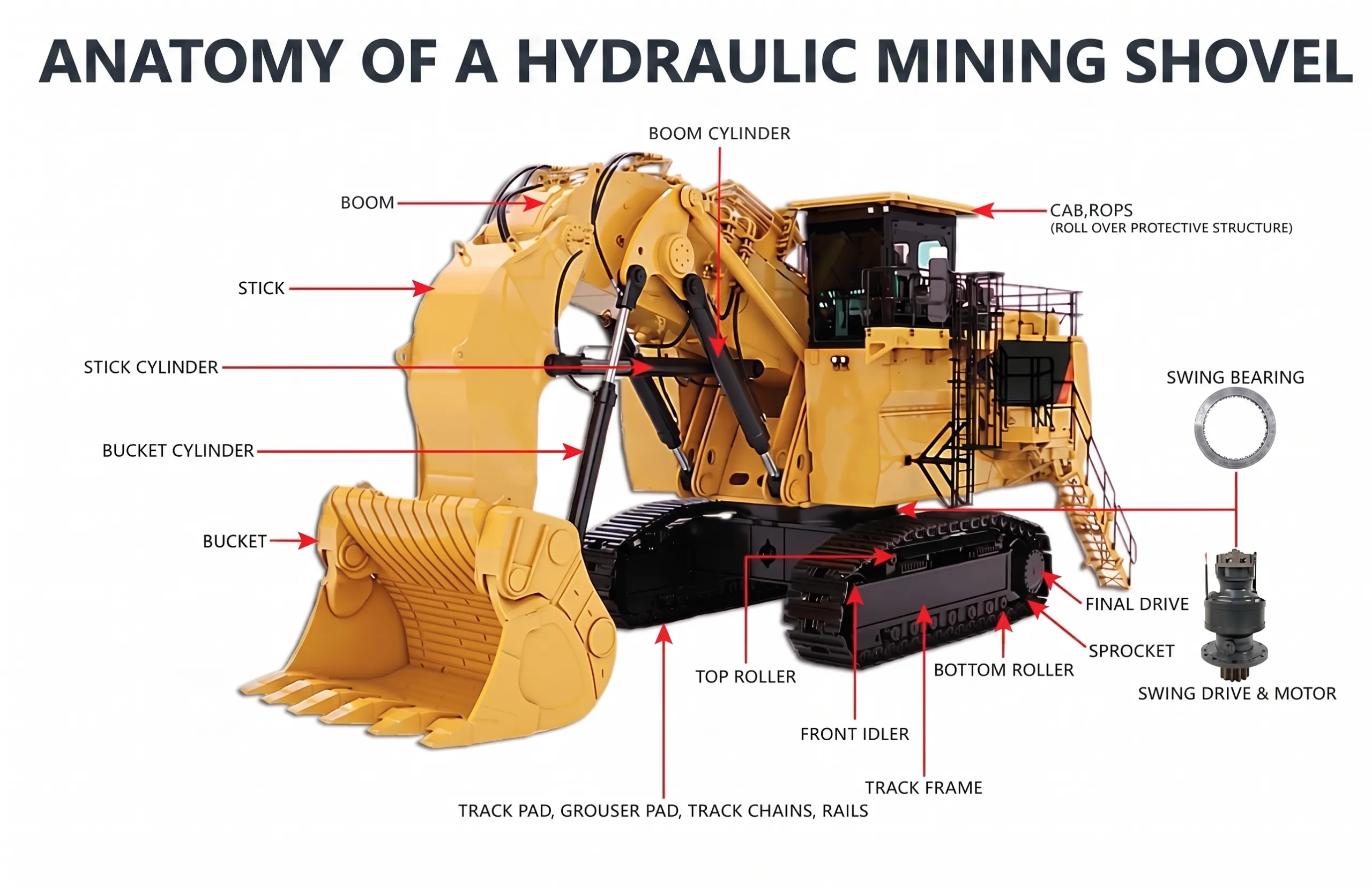
Major Components Of Heavy Equipment
Introduction
In the world of heavy equipment maintenance, there is a fundamental dividing line between a standard mechanic and an elite diagnostician. When a standard mechanic looks at a 50-ton excavator, they see a collection of separate parts: an engine, some hydraulic pumps, a few computers, and a steel boom. When an elite diagnostician looks at that same machine, they do not see isolated parts; they see a living, breathing, highly integrated ecosystem.
Understanding the major components of heavy equipment is not about memorizing a list of nouns. It is about understanding the verbs—how the engine drives the pump, how the ECU commands the valve, and how the tracks transfer the torque.
The industry is plagued by “parts changers”—mechanics who attempt to fix a machine by blindly replacing whatever component the fault code points to, without ever understanding why that component failed in the first place. Parts changing is expensive, inefficient, and dangerous.
This comprehensive guide is designed for the modern Diesel Fitter, Heavy Duty (HD) Mechanic, and OEM Field Service Technician. We will dissect the absolute architecture of heavy machinery, explaining not just what the components are, but how they interact. By mastering systems-thinking, you will evolve from a mechanic who fixes symptoms into a Diagnostic Leader who eliminates root causes.
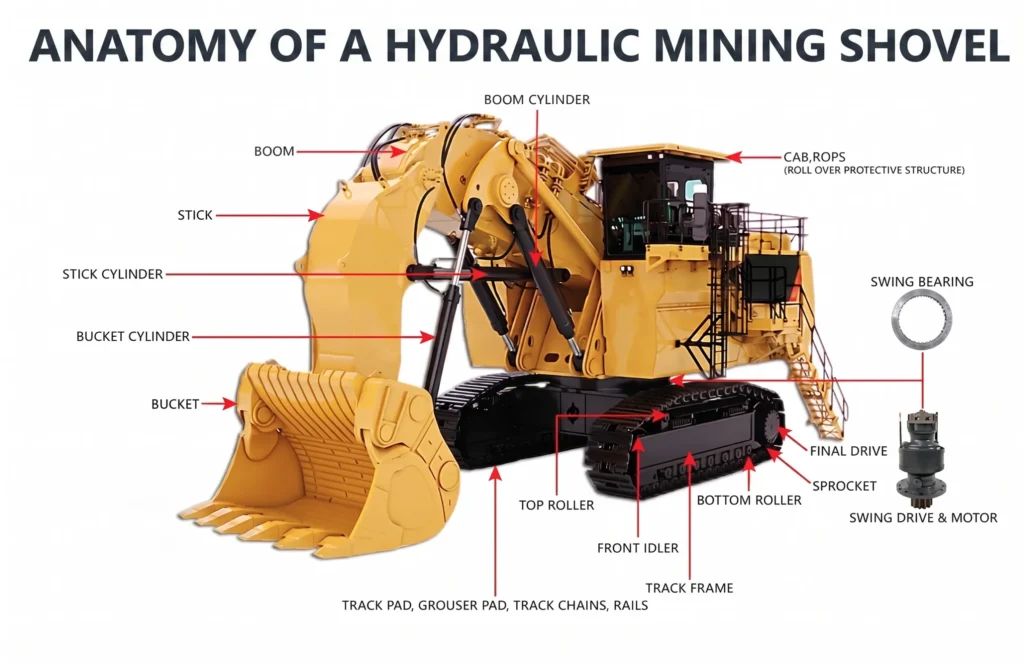
What Is Heavy Equipment?
“Heavy Equipment” is a broad umbrella term covering the massive, purpose-built machinery designed to execute severe-duty earthmoving, construction, and mining tasks. While their outward appearances vary wildly, their internal architectures share a common DNA.
- Excavators: Tracked or wheeled machines utilizing a boom, stick, and bucket to dig below machine level. Dominated by complex electro-hydraulic systems.
- Bulldozers (Track-Type Tractors): Massive tracked machines designed to push immense weight. Dominated by heavy powertrains and robust undercarriages.
- Wheel Loaders: Articulated rubber-tired machines used to scoop and load loose material. Characterized by high-flow hydraulics and complex torque-converter drivetrains.
- Motor Graders: Long-wheelbase machines with a belly-mounted blade used to create flat surfaces. Famous for incredibly intricate hydraulic control valves.
- Articulated Dump Trucks (ADTs): All-wheel-drive haulers with a central hinge, designed for extreme off-road mud and gradients.
- Rigid Haul Trucks: Massive mining trucks (up to 400-ton payloads) utilizing mechanical or AC electric-drive powertrains.
- Backhoes & Skid Steers: Compact utility machines featuring highly integrated, multi-function fluid power systems.
Regardless of the badge on the side—Caterpillar, Komatsu, Volvo, or Hitachi—every single one of these machines relies on the exact same fundamental systems architecture to function.
The Systems Thinking Approach
To diagnose modern iron, you must adopt this mantra: “A machine is a collection of integrated systems.”
A component rarely operates in a vacuum. The diesel engine provides the raw kinetic energy. The hydraulic system converts that kinetic energy into fluid power. The powertrain converts it into tractive effort. The electronic system monitors and commands the entire process, while the structural system physically withstands the resulting brutal forces.
If a machine is exhibiting “low power,” a parts changer immediately blames the engine. A systems thinker knows that a sticking load-sensing hydraulic valve might be forcing the pump to maximum displacement, dragging the engine RPM down and creating the illusion of an engine fault. You cannot fix the machine if you do not understand the system interaction.
Diesel Engine System
The diesel engine is the beating heart of the machine. It is the prime mover, responsible for converting the chemical energy of diesel fuel into rotational mechanical energy.
- Purpose: To spin the flywheel, which physically drives the main hydraulic pumps and the powertrain input shafts.
- Power Generation Process: Diesel engines use compression ignition. Air is compressed in the cylinder until it reaches immense heat; fuel is then injected and instantly ignites, driving the piston down.
- Interaction: The engine must physically interface with the hydraulic pumps via a gear train or flex coupling. It also relies heavily on the machine’s ECUs to calculate fuel delivery based on the load the hydraulic system is currently experiencing.
Fuel System
The fuel system is responsible for storing, cleaning, pressurizing, and delivering fuel to the combustion chamber with microscopic precision.
- Fuel Tanks & Lift Pumps: The tank stores the fuel, and a low-pressure transfer (lift) pump pulls it through primary filtration.
- Filters: Heavy equipment utilizes primary water separators (often 10-micron) and secondary high-efficiency filters (2-micron) to protect the injectors.
- High-Pressure Systems: Modern machines utilize High-Pressure Common Rail (HPCR) systems. A high-pressure pump generates up to 35,000 PSI, storing the fuel in a common rail. The Engine Control Module (ECM) then electrically fires the piezoelectric or solenoid injectors to deliver multiple micro-bursts of fuel per combustion stroke.
Air Intake And Turbocharger System
Diesel engines require massive volumes of clean air to burn fuel efficiently and control exhaust temperatures.
- Air Cleaners: Multi-stage centrifugal and paper filter housings designed to strip silica dust from the air before it enters the engine.
- Turbochargers: Exhaust gases spin a turbine wheel, which drives a compressor wheel, forcing dense, pressurized air (boost) into the cylinders.
- Charge Air Coolers (CAC / Intercoolers): Compressing air makes it hot. The CAC acts as a radiator for the air, cooling it down to make it denser before it enters the intake manifold, increasing engine power and reducing emissions.
Cooling System
The massive thermal energy generated by combustion and hydraulic friction must be dissipated, or the machine will melt down within minutes.
- Radiators & Coolers: A heavy equipment cooling package is actually a stack of multiple coolers: the engine jacket water radiator, the hydraulic oil cooler, the transmission oil cooler, and the charge air cooler.
- Water Pumps & Thermostats: A gear-driven pump circulates coolant through the engine block to absorb heat, while thermostats regulate the flow to the radiator to maintain an optimal operating temperature (usually 85°C – 95°C).
- Cooling Fans: Modern machines use hydraulically driven, electronically controlled variable-speed reversing fans. They only spin as fast as necessary to cool the hottest system, saving parasitic horsepower.
Lubrication System
Metal sliding against metal under high pressure requires a constant hydrodynamic film of oil to prevent friction welding.
- Oil Pumps & Coolers: A gear pump pulls oil from the sump, pushes it through an oil cooler to remove heat, and forces it through the engine block galleries.
- Filters & Bearings: High-efficiency filters remove soot and wear metals before the oil is injected between the crankshaft journals and main bearings, ensuring the components ride on a liquid film, never actually touching.
Powertrain System
If the engine is the heart, the powertrain is the legs. It takes the rotational energy of the engine flywheel and transfers it to the tires or tracks.
- Torque Converter / Fluid Coupling: A fluid-dynamic device that connects the engine to the transmission. It allows the machine to idle in gear without stalling and multiplies torque when digging into a pile.
- Transmission: Powershift transmissions use hydraulically applied clutch packs to change gear ratios under full engine load, altering the speed-to-torque output.
- Differentials & Final Drives: The differential splits power to the left and right wheels. The final drive (often a planetary gearset located in the wheel hub) provides the massive, final gear reduction, multiplying torque immensely right at the point where the rubber meets the dirt.
Hydraulic System
Hydraulics act as the muscular system of the machine. It is the most powerful and flexible method of transmitting energy across physical distances.
- Pumps: Driven by the engine, pumps convert mechanical rotation into fluid flow. Modern machines use complex variable-displacement axial piston pumps.
- Valves: Main Control Valves (MCVs) direct the high-pressure oil to specific circuits (boom, stick, bucket). Electro-proportional valves are commanded directly by the ECU.
- Actuators (Cylinders & Motors): Cylinders convert fluid power into linear motion (lifting a boom). Hydraulic motors convert fluid power into rotational motion (swinging the upper structure or driving the tracks).
- Reservoirs: Store the hydraulic oil, allow air bubbles to escape (de-aeration), and dissipate heat.
Electrical System
The electrical system is the nervous system. It provides the base power for everything from the starter motor to the main computer array.
- Batteries & Alternators: Heavy equipment universally runs on 24-volt DC systems. Two 12V batteries in series provide massive cranking amperage, while a heavy-duty alternator handles the running electrical load.
- Wiring Harnesses & Relays: Miles of heavily shielded copper wiring route power through relays (remote-controlled heavy-duty switches) to run massive lighting arrays, cab HVAC fans, and hydraulic solenoids.
- Fuses & Breakers: The critical safety net, designed to blow and cut power instantly if a circuit shorts to ground, preventing electrical fires.
Electronic Control Systems
Modern iron relies completely on digital logic. If the electrical system is the nervous system, the ECUs are the brain.
- ECUs (Electronic Control Units): Every major system has a dedicated computer. There is an Engine ECM, a Transmission Controller, and an Implement (Hydraulic) Controller.
- Sensors: These are the eyes and ears of the ECU. They translate physical realities (temperature, pressure, speed, physical geometry) into voltage signals the computer can understand.
- CAN Bus: The Controller Area Network. A twisted-pair wire that acts as a high-speed digital highway, allowing the Engine ECM to talk directly to the Hydraulic Controller.
Undercarriage System
For tracked machines (excavators, dozers), the undercarriage represents up to 50% of the machine’s lifetime maintenance cost.
- Track Chains & Shoes: The physical steel links and flat pads that grip the earth.
- Rollers & Idlers: Lower rollers support the machine’s weight on the track chain, while the massive front idler absorbs shock loads and manages track tension via a grease-filled recoil cylinder.
- Sprockets: Bolted to the final drive, the sprocket physically pulls the track chain to move the massive machine forward.
Structural Components
The skeleton of the machine. Structural components must withstand millions of cycles of brutal torsional twisting and lifting stresses.
- Frames: The massive, welded steel chassis. On an articulated dump truck, this involves a complex oscillating hitch that allows the front and rear frames to twist independently.
- Booms, Sticks, & Loader Arms: Heavy-duty box-section steel fabrications. They are designed to flex slightly under extreme load; if they were perfectly rigid, they would snap.
- Buckets & Wear Packages: The ground-engaging tools. Equipped with replaceable tungsten-carbide teeth and wear plates to absorb the highly abrasive friction of the dirt.
Braking Systems
Stopping a 100-ton machine carrying 60 tons of rock on a 10% downgrade requires immense engineering.
- Service Brakes: Usually oil-immersed, multi-disc wet brakes located inside the axles. They are cooled by hydraulic oil and actuate via high-pressure brake accumulators.
- Parking/Emergency Brakes: “Spring-applied, hydraulic-release” (SAHR) systems. If the machine loses hydraulic pressure or the engine dies, massive internal springs instantly clamp the brakes shut, ensuring the machine fails safely to a stop.
- Retarder Systems: Used on long downgrades to prevent service brake fires. Haul trucks use hydraulic transmission retarders or engine exhaust brakes to slow the machine without touching the physical wheel brakes.
Steering Systems
- Hydraulic Steering: On wheel loaders and haul trucks, turning the steering wheel opens an orbital valve, sending high-pressure hydraulic oil to massive steering cylinders that pivot the axles or the articulated frame.
- Electronic Steering (Steer-by-Wire): Modern machines have removed the steering wheel entirely, using CAN-bus joysticks to command proportional hydraulic steering valves electronically.
Operator Control Systems
The Human-Machine Interface (HMI).
- Joysticks: Electro-hydraulic pilot controls. Moving a joystick creates a micro-voltage signal sent to the ECU, which then commands a massive hydraulic pump to stroke up.
- Displays & Monitors: Full-color touchscreen tablets in the cab displaying engine health, rear-view camera feeds, and 3D GPS grading information.
Safety Systems
- ROPS & FOPS: Roll-Over Protective Structures and Falling-Object Protective Structures. The cab is an engineered steel cage designed to withstand the entire weight of the machine rolling onto its roof.
- Interlock Systems: Hydraulic lockout levers (the “deadman switch”) ensure the joysticks are completely deactivated when the operator exits the cab.
- Emergency Stops (E-Stops): Physical red buttons on the exterior bumper that instantly kill fuel delivery and apply the parking brakes in an emergency.
Telematics And Connectivity
The modern heavy machine is a rolling server rack.
- Fleet Monitoring & GPS: A cellular or satellite antenna on the roof constantly transmits the machine’s exact location, fuel burn, and payload efficiency to the cloud.
- Remote Diagnostics: OEM systems (like Cat Product Link or Komatsu KOMTRAX) allow a workshop supervisor sitting in an office to view active fault codes and live sensor data on a machine operating 500 miles away.
How All Systems Work Together (The Digging Cycle)
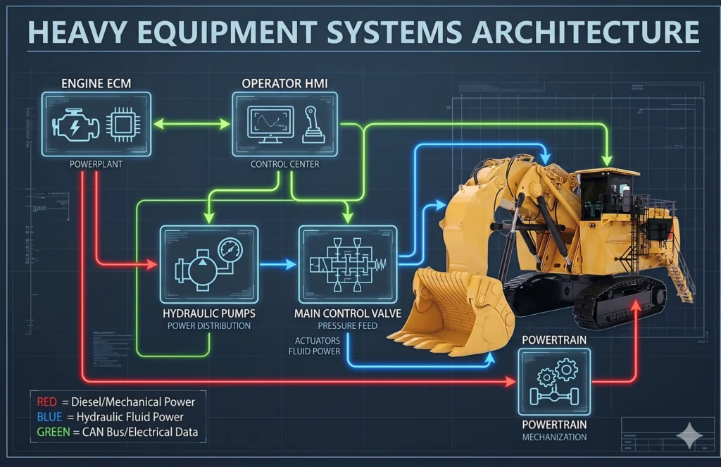
To be a Diagnostic Leader, you must visualize this entire chain of events occurring in milliseconds:
- The Command: The operator pulls back on the right joystick to curl the bucket.
- The Electronics: The joystick sends a 2.5V CAN-bus signal to the Hydraulic ECU.
- The Hydraulics: The Hydraulic ECU sends a PWM current to the Main Control Valve (MCV) proportional solenoid. The valve spool shifts, opening a path for oil to reach the bucket cylinder.
- The Load Sensing: The MCV sends a hydraulic or electronic load-sense signal back to the Main Hydraulic Pump, telling it to increase swashplate angle to meet the pressure demand of the dirt in the bucket.
- The Engine Integration: The Hydraulic Pump strokes up, placing a massive physical load on the engine flywheel, causing RPM to drop. The Engine ECM detects the RPM drop via the crank speed sensor.
- The Power Delivery: The Engine ECM instantly commands the HPCR fuel injectors to deliver more fuel. The turbocharger spools up to provide more air. The engine produces the requested torque, driving the pump, moving the cylinder, and curling the bucket through the rock.
Common Failure Chains
Machines fail in chains. Here is how systems impact one another.
- Dirty Air Filter → Reduced Boost Pressure → High Exhaust Gas Temp → Engine ECM Derates Fuel → Hydraulic Pump Lacks Drive Torque → Machine Lacks Digging Power.
- Failed V-Belt → Water Pump Stops → Engine Overheats → Cylinder Head Warps → Coolant Leaks into Engine Oil.
- Worn Hydraulic Pump → Metal Shavings Enter System → Shavings Lodge in Proportional Valve → Valve Sticks Open → Boom Drifts Down Autonomously.
- Corroded Battery Ground → High Electrical Resistance → Low Voltage to Engine ECM → ECM Reboots Continuously → Engine Stalls Intermittently.
- Clogged Transmission Filter → Oil Bypasses Filter → Debris Enters Clutch Packs → Clutches Slip and Burn → Machine Will Not Move in 3rd Gear.
- Failed Coolant Thermostat → Engine Runs Cold → Incomplete Diesel Combustion → Raw Soot Plugs DPF Filter → Severe Emissions Derate.
- Leaking Cylinder Rod Seal → Hydraulic Fluid Level Drops → Pump Draws in Air (Aeration) → Spongy Hydraulics and Overheating → Pump Cavitation and Destruction.
- Loose Track Tension → Track Chain Jumps the Sprocket (De-tracking) → Machine Immobility → Heavy Winching and Structural Damage to Recover.
- Stuck Brake Caliper → Constant Brake Drag → Extreme Brake Heat → Wheel Hub Seal Melts → Final Drive Gear Oil Leaks Out and Gears Shatter.
- Faulty Joystick Sensor → Erratic Voltage Sent to ECU → ECU Commands Valve to Open and Close Rapidly → Severe Hydraulic Spikes → Violent, Jerky Machine Movements.
Diagnostic Case Study: The Sluggish Excavator
Operator Complaint: “Machine is slow and lacks digging power. Engine sounds fine.”
The Parts Changer Approach: Assume the main hydraulic pump is bad. Order a $15,000 replacement pump. Install it. The machine is still slow. The customer is furious.
The Diagnostic Leader Approach:
- Symptom Verification: Operate the machine. Boom, stick, and bucket are all equally slow. Travel speed is normal.
- System Isolation: If travel speed is normal, the main pump is producing flow. The issue is likely in the implement control circuit, not the primary pump hardware.
- Data Analysis: Connect the diagnostic laptop. Check pilot system pressure. Normal is 600 PSI; actual reading is 250 PSI.
- Root Cause Identification: The pilot pump provides the pressure required to shift the massive spools in the Main Control Valve. Because pilot pressure is low, the spools are only opening halfway, severely restricting main oil flow to the cylinders. The mechanic finds a ruptured O-ring on the pilot pressure relief valve bypassing oil to the tank.
- Repair Validation: Replace a $2 O-ring. Pilot pressure returns to 600 PSI. The machine returns to full, aggressive digging speed. A $15,000 misdiagnosis was avoided through systems thinking.
Reliability Engineering Perspective
For the Reliability Engineer, understanding major components is an exercise in lifecycle management.
- Wear Mechanisms: Engineers track how abrasive dirt destroys undercarriage pins, and how thermal cycling destroys hydraulic hoses.
- Preventive Maintenance (PM): Using Scheduled Oil Sampling (SOS) to detect microscopic wear metals in the engine, hydraulic, and final drive oils to predict failures before they occur.
- Failure Prevention: If an engineer notes that 5 machines blew their hydraulic coolers in the same month, they analyze the system interaction and realize the operators are using an incorrect hydraulic hammer attachment that is overwhelming the return circuit bypass valve.
Workshop Leadership Perspective
Supervisors must build a workshop culture centered on systems knowledge.
- Training Technicians: Supervisors must ensure apprentices do not just learn how to rebuild a cylinder, but why the cylinder works within the load-sensing circuit.
- Building a Diagnostic Culture: When a technician asks for a new part, the supervisor must ask: “What data do you have to prove that part is the root cause?”
- Preventing Repeat Failures: If an engine fails due to a dusted turbocharger, the supervisor must ensure the technician also replaces the compromised charge air cooler, or the new engine will ingest the trapped dirt and fail immediately.
SPECIAL REQUIREMENT: Why Diagnostic Leaders Think In Systems
To survive the modern heavy equipment industry, you must abandon the “isolated component” mindset.
Diagnostic Leaders Think In Systems Because:
- Machines Fail As Systems: An overheating transmission is rarely a transmission problem; it is usually a cooling package problem (plugged radiator fins) or an operator problem (riding the brakes).
- Components Rarely Fail In Isolation: When a fuel injector tip blows off, it doesn’t just ruin the injector. The tip drops into the cylinder, scores the liner, shatters the piston rings, and sends metal through the turbocharger turbine. You must treat the entire failure radius.
- Root Cause Analysis Is Essential: The ECU fault code is merely a symptom. The code tells you where the pain is, not why it hurts. Systems thinking leads you to the “why.”
- Elite Technicians Understand Interactions: A master mechanic knows that fixing an electrical ground fault on the chassis can miraculously cure an intermittent hydraulic stalling issue.
This publication, Modern Trade Skills, exists to elevate the trade. The industry does not need more mechanics who can swap parts quickly. The industry desperately needs professionals who can look at a 100-ton machine, visualize the invisible flow of electrons, fuel, and hydraulic oil, and logically isolate the defect. We are dedicated to Developing Diagnostic Leaders Rather Than Parts Changers.
What This Means For Apprentices
If you are an apprentice entering the trade, the complexity of these massive machines can be terrifying. Do not panic.
- Why Systems Knowledge Matters: Do not try to memorize every bolt on a Caterpillar D10 dozer. Instead, learn how a basic load-sensing hydraulic system works. Once you understand the concept, you can apply that knowledge to a Cat dozer, a Komatsu excavator, or a John Deere grader. The physics are identical.
- How Elite Technicians Think: They read the “Theory of Operation” section in the service manual before they ever pick up a wrench.
- Accelerate Your Career: Apprentices who spend their evenings studying electrical schematics and hydraulic flow charts will be promoted to field service diagnostic roles years faster than those who only focus on getting dirty.
Summary And Key Takeaways
- A Machine is an Ecosystem: Never troubleshoot a single component without considering the upstream inputs and downstream outputs.
- The Engine is the Prime Mover: It converts chemical energy (diesel) into the rotational energy that drives the entire machine.
- Hydraulics are the Muscle: They transfer massive amounts of energy flexibly across the machine to do the heavy lifting.
- The Powertrain Transfers Torque: It converts engine RPM into the brutal tractive effort required to move earth.
- ECUs are the Brains: Computers manage and optimize the interaction between the engine, hydraulics, and powertrain based on operator demand.
- Sensors Provide the Senses: Without inputs from temperature, pressure, and speed sensors, the ECUs are blind.
- CAN Bus is the Nervous System: High-speed twisted-pair wiring allows all the ECUs to communicate instantly.
- Thermal Management is Critical: The cooling system prevents the catastrophic failure of engines, hydraulics, and transmissions under heavy load.
- Undercarriages are Expensive: Tracked systems are high-wear components that require constant measurement and tension management.
- Safety Systems are Non-Negotiable: SAHR brakes and E-stops ensure a machine fails safely if the primary systems die.
- Look for the Root Cause: The failed component is often the victim of a failure in a completely different system.
- Master the Basics: You cannot diagnose a multiplexed CAN bus network if you do not understand basic Ohm’s law.
- Data is King: Telematics and electronic diagnostic tools give you the internal visibility required to fix modern iron.
- Read the Manual: The Theory of Operation is the most important section of any OEM literature.
- Become a Diagnostic Leader: Use logic, data, and systems thinking to fix the machine right the first time.
FAQ SECTION
Q1: What are the major systems in heavy equipment? A: The core systems are the Diesel Engine, Hydraulics, Powertrain, Electrical/Electronic Control, Undercarriage/Wheels, Structural frames, and Operator/Safety controls.
Q2: Which system fails most often? A: Hydraulic hoses and electronic sensors have the highest failure frequency due to constant exposure to high pressure, vibration, and harsh environmental conditions.
Q3: Why are hydraulics so important? A: Hydraulics provide immense force density. A relatively small hydraulic cylinder can generate hundreds of thousands of pounds of breakout force, which would be impossible with traditional mechanical gear reductions.
Q4: What is the role of an ECU? A: The Electronic Control Unit (ECU) acts as the brain. It reads sensor data (inputs), calculates logic based on its programming, and commands actuators like fuel injectors or hydraulic valves (outputs) to operate the machine efficiently.
Q5: How do systems interact? A: If an operator commands maximum hydraulic flow, the hydraulic ECU tells the pump to stroke up. The pump puts a load on the engine. The engine RPM drops. The Engine ECM detects the drop and instantly commands more fuel to maintain the RPM.
Q6: What is a powertrain in heavy equipment? A: The components that transfer power from the engine to the ground. This includes the torque converter, transmission, driveshafts, differentials, and final drives.
Q7: What is the difference between a service brake and a parking brake? A: Service brakes are hydraulically applied by the operator to slow the machine. Parking brakes are spring-applied and hydraulically released (SAHR); if the machine dies and loses hydraulic pressure, the massive springs automatically clamp the brakes shut.
Q8: Why do excavators use tracks instead of wheels? A: Tracks provide a massive “footprint” that distributes the heavy weight of the machine over a large surface area, dramatically reducing ground pressure so the machine doesn’t sink in mud, while providing superior digging traction.
Q9: What is a CAN Bus? A: The Controller Area Network. It is a high-speed communication wiring network that allows all the different computers on the machine to talk to each other, sharing data like engine speed and hydraulic pressure.
Q10: Why do technicians use diagnostic laptops? A: Because modern machines are electronically controlled, technicians must plug laptops into the machine’s diagnostic port to view live sensor data, read active fault codes, and flash new software to the ECUs to diagnose complex system failures.
Q11: What is a final drive? A: The last gear reduction in the powertrain, located right at the wheel hub or track sprocket. It uses a planetary gearset to drastically slow down rotational speed while massively multiplying torque.
Q12: How does a turbocharger work? A: It uses waste exhaust gases to spin a turbine, which is connected to a compressor wheel. The compressor sucks in fresh air, compresses it, and forces it into the engine, allowing the engine to burn more fuel and make more power.
Q13: What does the charge air cooler do? A: Compressing air with a turbocharger makes it very hot. The charge air cooler acts like a radiator for the air, cooling it down to make it denser before it enters the engine cylinders.
Q14: Why is contamination control so important? A: Modern hydraulic valves and diesel fuel injectors have internal clearances measured in microns (smaller than a human hair). A single grain of dirt can jam a valve or destroy a $2,000 injector instantly.
Q15: What is a Diagnostic Leader? A: A technician who uses system knowledge, diagnostic software, electrical testing, and hydraulic theory to pinpoint the exact root cause of a failure, rather than blindly replacing expensive parts based on guesswork.
DIGITAL PRODUCT OPPORTUNITIES
Accelerate your understanding of machine architecture with these exclusive Modern Trade Skills digital resources:
- Heavy Equipment Systems Handbook: A comprehensive PDF guide detailing the fluid power and electrical circuitry for the 5 most common earthmoving machines.
- Machine Systems Wall Chart: A high-resolution, printable poster visually mapping the CAN bus and hydraulic interactions across a standard excavator.
- Apprentice Learning Workbook: An interactive study guide covering foundational diesel thermodynamics, basic Ohm’s Law, and hydraulic leverage calculations.
- Systems Interaction Flowcharts: A series of diagnostic logic trees showing how a fault in one ECU cascades into symptoms across the rest of the machine.
- Diagnostic Thinking Workbook: A scenario-based training tool designed to break the “parts changer” habit by forcing technicians to perform root-cause analysis on paper before touching a wrench.